


Components
|
|
Led (Package : SMT 1206) |
x 60 | |
|
|
Resistor (Package : SMT 1206) |
x 8 | |
|
|
Connectors |
x 2 | |
|
|
This Board |
x 1 |
Description
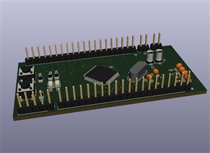
Custom Designed Seven Segment Display
Led is very basic component in the design and some time led do lot more work than just indication.
In this article we will see how to build custom designed seven segment display using led.
There are lot of variety of seven segment in the market but i choose to build my own because of i had time and many leds laying around me.
I have used Kicad tool for schematic and PCB designing.
Here is the complete Guide:
Here is the code:
#define SEGMENT_A  5
#define SEGMENT_B 6
#define SEGMENT_C 7
#define SEGMENT_D 8
#define SEGMENT_E 9
#define SEGMENT_F 10
#define SEGMENT_G 11
//#define SEGMENT_dp

#define SEG_SELECT_1  A3
#define SEG_SELECT_2  A2
#define SEG_SELECT_3  A1
#define SEG_SELECT_4  A0

#define SEGMENT_SWITCH_DELAY  5
int CounterPeriod = 1000;
unsigned long time_now = 0;
/*
    a
   --
  |  |
 f|g |b
   --
  |  |
 e|  |c
   --
   d

Byte = hgfedcba
*/
uint8_t segmentdecode[] = {0x3F,0x06,0x5B,0x4F,0x66,0x6D,0X7D,0X07,0X7f,0X6f,0X77,0x7C,0x39,0x5E,0x79,0x71};

void DisplayNum(uint8_t num)
{
    digitalWrite(SEGMENT_A, (num & 0x01)?HIGH:LOW);
    digitalWrite(SEGMENT_B, (num & 0x02)?HIGH:LOW);
    digitalWrite(SEGMENT_C, (num & 0x04)?HIGH:LOW);
    digitalWrite(SEGMENT_D, (num & 0x08)?HIGH:LOW);
    digitalWrite(SEGMENT_E, (num & 0x10)?HIGH:LOW);
    digitalWrite(SEGMENT_F, (num & 0x20)?HIGH:LOW);
    digitalWrite(SEGMENT_G, (num & 0x40)?HIGH:LOW);
}

void setup() {
  // put your setup code here, to run once:
    pinMode(LED_BUILTIN, OUTPUT);
    pinMode(SEGMENT_A, OUTPUT);

    pinMode(SEGMENT_A, OUTPUT);
    pinMode(SEGMENT_B, OUTPUT);
    pinMode(SEGMENT_C, OUTPUT);
    pinMode(SEGMENT_D, OUTPUT);
    pinMode(SEGMENT_E, OUTPUT);
    pinMode(SEGMENT_F, OUTPUT);
    pinMode(SEGMENT_G, OUTPUT);
//    pinMode(SEGMENT_dp,OUTPUT);

    pinMode(SEG_SELECT_1, OUTPUT);
    pinMode(SEG_SELECT_2, OUTPUT);
    pinMode(SEG_SELECT_3, OUTPUT);
    pinMode(SEG_SELECT_4, OUTPUT);
}

int i;
int Counter=0;
int convertedInUnit[4];
//1234
void DisplayOnSegment(int d)
{
  convertedInUnit[0] = d/1000;
  digitalWrite(SEG_SELECT_1, HIGH);
  digitalWrite(SEG_SELECT_2, LOW);
  digitalWrite(SEG_SELECT_3, LOW);
  digitalWrite(SEG_SELECT_4, LOW);
  DisplayNum(segmentdecode[convertedInUnit[0]]);
  delay(SEGMENT_SWITCH_DELAY);
  DisplayNum(0x00);//1

  convertedInUnit[1] = (d%1000)/100;
  digitalWrite(SEG_SELECT_1, LOW);
  digitalWrite(SEG_SELECT_2, HIGH);
  digitalWrite(SEG_SELECT_3, LOW);
  digitalWrite(SEG_SELECT_4, LOW);
  DisplayNum(segmentdecode[convertedInUnit[1]]);
  delay(SEGMENT_SWITCH_DELAY);
  DisplayNum(0x00);//2

  convertedInUnit[2] = ((d%1000)%100)/10;
  digitalWrite(SEG_SELECT_1, LOW);
  digitalWrite(SEG_SELECT_2, LOW);
  digitalWrite(SEG_SELECT_3, HIGH);
  digitalWrite(SEG_SELECT_4, LOW);
  DisplayNum(segmentdecode[convertedInUnit[2]]);
  delay(SEGMENT_SWITCH_DELAY);
  DisplayNum(0x00);//3

  convertedInUnit[3] = ((d%1000)%100)%10;
  digitalWrite(SEG_SELECT_1, LOW);
  digitalWrite(SEG_SELECT_2, LOW);
  digitalWrite(SEG_SELECT_3, LOW);
  digitalWrite(SEG_SELECT_4, HIGH);
  DisplayNum(segmentdecode[convertedInUnit[3]]);
  delay(SEGMENT_SWITCH_DELAY);
  DisplayNum(0x00);//4
}

void loop() {
  if(millis() > time_now + CounterPeriod)
  {
    time_now = millis();
    Counter++;
    if(Counter > 9999)
    {
      Counter = 0;
    }
  }
 DisplayOnSegment(Counter);
}
Here is github link for more details:
https://github.com/stechiez/electronicsDIY/tree/master/CustomSevenSegmentDisplay
Code
https://blogs.stechiez.com/2020/03/28/custom-designed-seven-segment-using-led/
Schematic and Layout
https://blogs.stechiez.com/2020/03/28/custom-designed-seven-segment-using-led/
Mar 19,2020
2,512 views
Custom Designed Seven Segment Display
This is a very useful custom designed Led seven segment display module.
2512
10
3
8.33 (6)
Published: Mar 19,2020
Download Gerber file 22
PCBWay Donate 10% cost To Author
*PCBWay community is a shared platform and we are not responsible for any design issues.


Under the
Attribution-ShareAlike (CC BY-SA)
License.


- Comments(3)
- Likes(10)
You can only upload 1 files in total. Each file cannot exceed 2MB. Supports JPG, JPEG, GIF, PNG, BMP
0 / 10000
VOTING
6 votes
- 6 USER VOTES
8.33
- YOUR VOTE 0.00 0.00

-
6design
-
8usability
-
7creativity
-
9content
7.50

-
9design
-
9usability
-
9creativity
-
10content
9.25

-
9design
-
9usability
-
9creativity
-
9content
9.00

-
10design
-
7usability
-
8creativity
-
10content
8.75

-
7design
-
7usability
-
7creativity
-
7content
7.00

-
9design
-
9usability
-
8creativity
-
8content
8.50
 More by Emb-dev
-
 USB to UART Converter module
This is the pcb design file for USB to Serial converter. In this design i have used CH340 USB to ser...
USB to UART Converter module
This is the pcb design file for USB to Serial converter. In this design i have used CH340 USB to ser...
-
 Raspberry Pico with Ultrasonic Sensor and SSD1306
In this article, we will see how to interface Ultrasonic sensor and OLED with Raspberry Pi Pico usin...
Raspberry Pico with Ultrasonic Sensor and SSD1306
In this article, we will see how to interface Ultrasonic sensor and OLED with Raspberry Pi Pico usin...
-
 Microchip PIN-44 Developement Breakout Board
This design is for PIC 44 pin SMD Controller. I have designed this board as initial version which wi...
Microchip PIN-44 Developement Breakout Board
This design is for PIC 44 pin SMD Controller. I have designed this board as initial version which wi...
-
 Custom Designed Seven Segment Display
Led is very basic component in the design and some time led do lot more work than just indication.In...
Custom Designed Seven Segment Display
Led is very basic component in the design and some time led do lot more work than just indication.In...
You may also like
-
-
(DIY) COMMODORE 64 DEAD-TEST (781220) DIAGNOSTIC CARTRIDGE
210 0 2 -
Creative Micro Designs Inc. CMD FD-2000 / FD-4000 3D Printable Case
301 0 0 -
Creative Micro Designs Inc. CMD FD-2000 / FD-4000 Metal Case
434 0 0 -
-
-
IoT Indoor system with ESP32 to monitor Temperature, Humidity, Pressure, and Air Quality
919 0 3


