How to Build a Real Time Clock with a PICAXE
Adding a real time clock (RTC) circuit and a digital display to a microcontroller to create a functional clock is a favorite undertaking for many electronics DIYers.
Step 1: How to Build a Real Time Clock with a PICAXE
Real Time Clock Modules
A real time clock module consists of an RTC integrated circuit plus the peripheral components necessary to support the clock chip, all of which have all been assembled on a custom printed circuit board. A example of such a module is shown in the photograph below.
.png)
This particular RTC module is the author's own design, but is more or less representative of many other designs. At the top center is the RTC chip which, in this case, is a DS1307 from Maxim Integrated. To the left of the DS1307 is a 32.768 MHz crystal, and below the crystal is a 3V backup battery to keep the DS1307 running when external power is interrupted. The green LED lights to show that external power is connected, and the ceramic capacitor filters the power to the DS1307. The pin header labeled "PH5" connects the module to power and other external circuitry. The three resistors are pull-ups for three of the signal leads.
Why a DS1307?
The DS1307 is not the newest RTC around, nor is it the most accurate, so why use it? There are two main reasons: first, it is widely used and available at very low prices, and second, it uses I2C (say "eye squared see") signalling. A quick on-line search will locate DS1307 modules from US and international suppliers. Some modules will have only the DS1307 IC, and others may add an AT24C32 or some other EEPROM chip; the programmable memory isn't used in this project, but it won't cause any problems if it's included.
I2C signalling is mandatory for the code in this project. It requires only two wires for communication with the microcontroller: a serial data line (SDA,) and a serial clock line (SCL,) and both are potentially bi-directional. There is lots more to learn about I2C, and you are encouraged to look into it, but an in-depth knowledge is obviated by the amazing capabilties of the PICAXE system.
In general, any RTC module is usable for this project as long as it meets the following requirements.
- Uses a DS1307
- Operates on 5VDC and provides connection points for +5Vin and ground
- Provides easy access to the SDA and SCL leads
Header pins are often used as connecting points; see the photo below. (Access to the Vbat and SQW leads is not required.)

Of course, you can also build your own RTC circuit as described here as long as it meets the requirements stated above.
Circuit Diagram and Breadboard Assembly
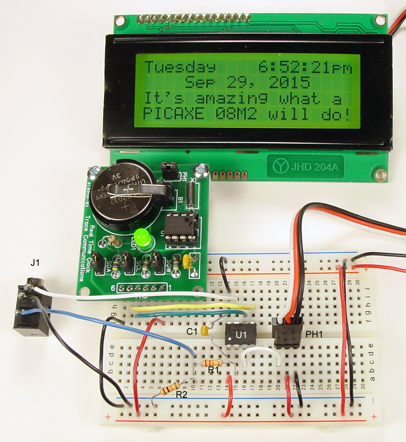
As you see, the circuit is quite simple. The RTC module comprises all the parts inside the red rectangle, and is connected via four wires to the PICAXE. The display is equipped with an LCD117 serial backpack adapter, which is connected to the 08M2 by only three wires via PH1.

The photo below shows the the RTC module, the solderless breadboard assembly, and the display; the project is fully functional. Note that the wire colors noted on the schematic above correspond to the actual wire colors that were used in the solderless breadboard assembly.
Of course the physical appearance of your assembly will vary from the photograph to accommodate the DS1307 RTC module you use. The electrical configuration should be identical to both the schematic and the photograph.

- Comments(0)
- Likes(2)