Introduction:
Today, I would like to ask you a question, when you are just a beginner in the PCB field, whether it is the same as me, every time I see the circuit diagram, I think "oh my god! Am I a fool? If not, why can't I read any of these circuit diagrams and why on earth am I taking this course?”
I think a lot of people will be confused as me, when we face the crisscross dense lines but do not know how to start. In fact, circuit diagrams are easy to understand and easy to use. The key is not to be fooled by its appearance. Some circuit diagrams that we can often use in life are electronic circuit, amplification circuit, crystal oscillation circuit and power circuit and so on. Here are some circuit diagrams we may meet in our dairy life as following.
Figure 1:
PS: ① The numbers in【】in this circuit diagram is the path circuit diagram of signal.
② 》 in this circuit diagram is signal pattern.
③ 《》 in this circuit diagram is bidirectional signal pattern.
First of all, let's take a look at the circuit diagram above. This is the e-compass + Acc of a smart phone, which is also equivalent to a compass. Smartphones use it to map locations. The circuit diagram below is not very simple. For example, if something goes wrong with our electronic compass, we usually first check whether the voltage of the voltage circuit is normal. If the result shows normal, then next, we will check whether the I2C bus line is normal. And then we can easily determine whether there is an exception in U801 ontology.
Figure 2:
IR is now ubiquitous in electronic products, because it is not only convenient, simple, and very practical, so that smart phones, remote air conditioning, smart TV and other electronic products have become an indispensable part of our life.
This circuit is composed of IR control chip U802, power supply chip U808 and IR_LED diode. If there is a problem with IR, we will first analyze whether there is a problem with the voltage output of U808 power supply chip. If this is not a problem, then we will check the U802 control chip signal is normal. If all else is ok, then we will finally check whether the IR_LED diode is damaged or not.
My trick with circuit diagrams is to analyze and examine them in parts, not in whole. In fact, as long as we can find a reasonable way to analyze the circuit diagram, then the circuit diagram is not as difficult as we imagine.
Figure 3:
EMMC is the phone body memory, which is often said in the market, 16GB, 32GB, 64GB, 128GB and so on. The line is not very complicated. For example, if there is a problem with this circuit, we will first check the power supply circuit and then analyze the signal circuit, and the relevant IC is EMMC and CPU. Generally speaking, if there is something wrong with the CPU, we generally do not recommend to repair because the maintenance cost is very high.
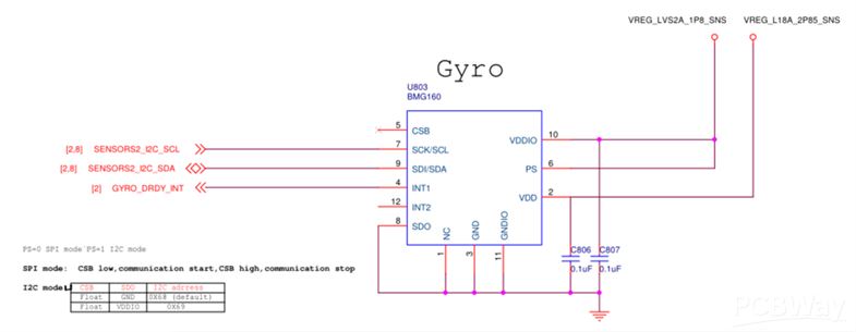
Figure 4:
The Sensor-GYRO in a smartphone is a device that senses and maintains direction based on the conservation of angular momentum, which it is an indispensable and important function in smart phones.
Figure 5:
Hall Effect Switch: when a piece of metal or semiconductor with current is placed vertically in the middle of a magnetic field, the potential difference between the two ends of the sheet will be generated. This phenomenon is called Hall Effect. For example, there is a magnetic disk on the phone case, when our phone case is closed, the screen will go out.
Figure 6 & 7: