


Digital to analog conversion is very old technology. This conversion helps to create sound from digital media. This digital media can be MP3, MP4 songs. There are many applications of these conversions. What I noticed that in many our university curriculum, they prescribed that you have to use DAC0808 IC to do this conversion experiment.
I tried to do this experiment for our one client; I noticed that it requires ‘negative -12 voltage” power supply and cost of that power adapter is added in the experiments. Nowadays budget of polytechnic colleges is reducing day by day. I decided to read and do experiment with alternate DAC IC. Fig 1 shows interfacing of 8051 with DAC0808 IC. I am not explaining this experiment. You can notice -12V supply in the circuit.
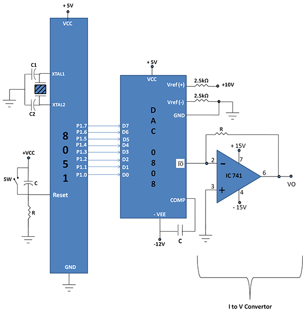
Fig 1 Interfacing of DAC0808 with 8051 microcontroller.
We will see alternate DAC0832 IC interface to 8051. Let’s study brief about DAC0832 IC. Fig 2 shows pin diagram of DAC0832 IC. It is 20 PIN DIP(Dual –in-Line Package) IC
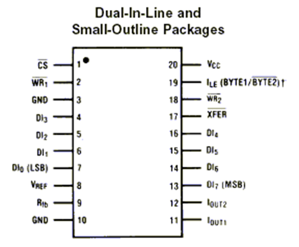
Fig 2 Pin diagram of DAC0832
The DAC0830 is an advanced CMOS/Si-Cr 8-bit multiplying DAC designed to interface directly with the 8080, 8048, 8085, Z80, and other popular microprocessors. A deposited silicon-chromium R-2R resistor ladder network divides the reference current. The circuit uses CMOS current switches and control logic to achieve low power consumption and low output leakage current errors. Special circuitry provides TTL logic input voltage level compatibility.
Double buffering allows these DACs to output a voltage corresponding to one digital word while holding the next digital word. This permits the simultaneous updating of any number of DACs.
Technical specification of this IC:
- Double-Buffered, Single-Buffered or Flow-Through Digital Data Inputs
- Easy Interchange and Pin-Compatible with 12-bit DAC1230 Series
- Direct Interface to All Popular Microprocessors
- Linearity Specified with Zero and Full Scale Adjust Only—NOT BEST STRAIGHT LINE FIT.
- Works with ±10V Reference-Full 4-Quadrant Multiplication
- Can Be Used in the Voltage Switching Mode
- Logic Inputs Which Meet TTL Voltage Level Specs (1.4V Logic Threshold)
- Operates “STAND ALONE” (without μP) if Desired
- Available in 20-Pin SOIC or PLCC Package
Interfacing of 0832IC with 89s52 microcontroller is shown in Fig3. You can replace this microcontroller with P89v51RD2 IC. I explained P89v51RD2 microcontroller in my other article. This microcontroller easily programmable via serial port(COM port) using FlashMagic utility (This utility can be downloaded from link www.flashmagictool.com/)

Fig 3: Interfacing of DAC0832 IC with 89s52 microcontroller.
This microcontroller you can program using EPROM programmer or Universal programmer.
In embedded market independent DAC0832 modules are available for sale. I picked up one module which we use for our client. Fig 4 shows front side of DAC module and Fig 5 shows back side of DAC0832 module.
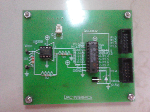
Fig 4: front side of DAC0832 module
You type following program in evaluation keil version cross compiler. Create HEX file for this experiment and download that HEX file in the 8051 board. We are using Port P1 of 8051 to interface DAC module. Connect P1.0 to P1.0 of DAC module so on, you connect al 8 pins of Port1 to DAC module. Digital data is coming from 8051 microcontroller. DAC0832 will convert this data in to analog. We are using P3.3, P3.4, P3.5 pins for hand shaking of 8051 and DAC0832 IC. Connect P3.3 of microcontroller to active low CS signal of DAC0832 module and P3.4, P3.5 for WR1 and XFER respectively.
1)To generate sine wave through DAC 0832: Type this program.
The program is provided in above Sourcecode Section.
Above program is very easy to understand. We select IC by making CS=0 in program. We are using super loop to show sine wave continuously at VOUT and GND signal of DAC0832 board.
We are making WR1,XFER signal 1 in program to tell DAC that start of conversion. WAVEVALUE[i]; statement is transferring digital value form array to P1 of 8051. These values are 12 values and you can increase these values for better result. We are making WR1, XFER signal to “0” and creating delay using _nop_(); statement multiple times.
Once conversion happens, we are sending analog output via LM358 to amplify analog signal. LM358 details are explained in other articles of engineersgarage website (http://www.engineersgarage.com/contribution/anjali/performing-experiments-with-lm358) .
You can check sine wave output from DAC0832 module on CRO by connecting Channel probe of CRO at Vout and GND of DAC module. Fig 5 shows sine wave output. As we are providing 12 digital value, we are not getting super fine Sine wave, but by increasing values of Array, we can get better sine wave.
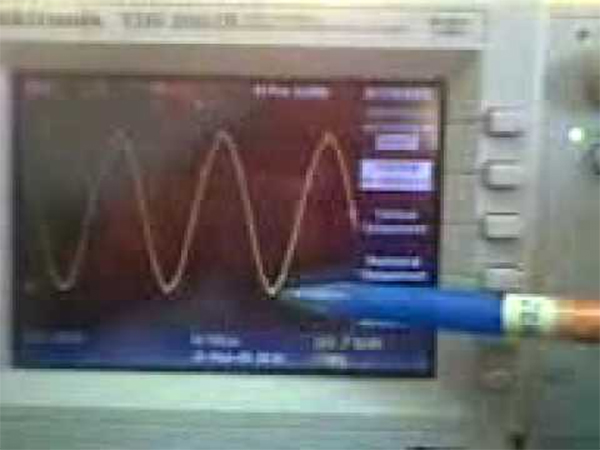
Fig 5: Sine wave form generation using DAC0832 module.
2)To generate triangular wave from DAC0832: Type following program in Keil version 3 cross compiler.
|
/************************************************************************************* This program generates a triangular wave of 2kHz when Port1 in interfaced with DAC **************************************************************************************/ The Program is provided in the above Sourcecode section. |
Above program is very simple to understand. We are sending P1 += 0x05;
Value to port P1 of 8051 and these values are controlling DAC0832. We are sending incremental values using following loop.
do
{
WR1=1;
XFER=1;
P1 += 0x05;
WR1=0;
XFER=0;
}
while(P1<0xFF);
Microcontroller keep sending data from 0x05 to 0xFE and when this data become 0xFF, it comes out from loop and we are getting RAMP output due to this loop. In second loop we are decrementing value using
P1 -= 0x05;
Statement and again testing for P1< 0xFF, as in first loop, we incremented and second loop we decremented value of P1, we are getting triangular waveform. Fig 6 shows triangular wave.
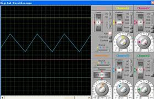
Fig 6 Triangular waveform generated by DAC0832 Module using 8051 interfacing.
3)To generate square wave using DAC0832 module :Tyep ethis program in keil version 2 and generate HEX file and download indidually to get square wave.
|
/********************************************************************************* This program generates a square wave of 2kHz when Port1 in interfaced with DAC ***********************************************************************************/ The program is provided in the above Sourcecode Section. |
We are sending 0xFF and 0x00 value from the Port 1 of 8051 and this will enter in to DAC0832 IC which process digital data and gives out Analog output. In this code, we are writing separate void delay(int time) function. This function is having one argument ‘time”, whenever we call this function in main program, we have to pass some integer number. In above code, we are writing delay(1);, this pass “1” and value of time will become 1 inside delay() function.
We are using simple for loop to create delay, you have to understand that upper for loop is not having semicolon and inner for loop is having semicolon. There is typical meaning to that. When you want to execute inner loop completely then we write like this code. Here initial value of “i” will be “0” and internal loop will be executed three times where j=0, j=1 and j=2 then conditions in the for loop will be false and processor will come out from inner loop. Then again “i” will incremented to “1”. This is happening due to i++ statement.
for(i=0;i<=time;i++)
for(j=0;j<=2;j++);
Fig 7 shows output of square wave using DAC0832 module.
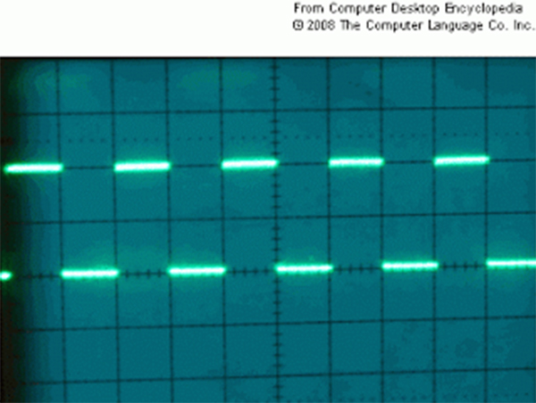
Fig 7 Square wave output of DAC0832

 Log in to post comments.


