|
|
27c512 EPROM |
x 5 | |
|
|
27c160 EPROM |
x 1 | |
|
|
ATTiny 13, 25, 45, or 85 |
x 1 | |
|
|
Push button |
x 1 | |
|
|
Round socket strip |
x 1 | |
|
|
Round header strip |
x 1 | |
|
|
Patch wire |
x 1 | |
|
|
Pull-up resistor |
x 1 |

|
arduino IDEArduino
|
|

|
Python |
Arkanoid-Multi PCB v1.1
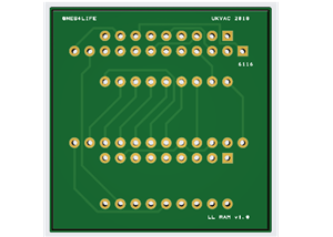
The Arkanoid-multi holds Arkanoid and Tournament Arkanoid ROMs on a signle original arcade board and bank-switches them with an ATTiny. Press and hold the on-board button or wire-up an external button to switch between games.
GitHub documentation and Gerbers:
https://github.com/Phillrb/arkanoid_multi
Original KLOV thread:
https://forums.arcade-museum.com/threads/arkanoid-freeplay-rom.508179/post-4567644
Use this in conjunction witjh the MCU Bypass PCB:
https://www.pcbway.com/project/shareproject/Arkanoid_MCU_Bypass_PCB_v1_2_2c4eb5f2.html
MCU-Bypass documentation:
https://github.com/mdeslaur/arkanoid-mpu-bypass
Burn ATTiny
The binary in 'ATTiny85_Bankswitch' can be burnt to an ATTiny85.
Hold the button for 4 seconds to switch game.
If you would like a different switching mechanism, or you want to target a different ATTiny (13, 25 or 45), then all the code can be found at the Multi ROM Controller repo on GitHub.
Construct Mod
The Arkanoid-Multi PCB fits into the three sockets from the color PROMs and hosts the 27c160, ATTiny and a push button. Please keep your original ICs safe as you may want to remove the mod in the future.
The A0 line needs to be wired to pin 1 of all five 27c512 EPROMs. Pin 1 should not make a connection with the hosting PCB. These EPROMs should be fitted into round turned-pin socket strips. Heat up and remove the round pin socket that pin 1 of the EPROM will go into so that there is an air-gap between pin 1 and the hosting PCB. You may need to slightly trim pin 1 of the EPROM so that it doesn't make contact.
Wire the NXT line to an external button. Arkanoid conveniently has 'P1 button 2' on the edge connector wired up (22) but does not make use of it, or alternatively use the 'P1 Start button' (12). Arkanoid is 'Taito Classic' pinout.
The last line that needs to be hooked up is the RST line. Solder a wire from it to pin 1 of IC32 (LS273) as this is the CPU reset line.
Arkanoid Freeplay ROM Dipswitch Settings
DIPS -> OFF or ON
- Cocktail or Upright
- Credit or Freeplay
- Lives 3 or 5
- Bonus at 20K/60K or 20k only
- Difficulty Easy or Hard
- Test mode off or on
- Screen Normal or Inverted
- Continued play off or on
Arkanoid-Multi PCB v1.1
*PCBWay community is a sharing platform. We are not responsible for any design issues and parameter issues (board thickness, surface finish, etc.) you choose.
- Comments(1)
- Likes(2)
-
 Phillip NES4Life
Oct 31,2025
-
 Валентин Матвиенко
Oct 28,2022
- 1 USER VOTES
- YOUR VOTE 0.00 0.00
- 1
- 2
- 3
- 4
- 5
- 6
- 7
- 8
- 9
- 10
- 1
- 2
- 3
- 4
- 5
- 6
- 7
- 8
- 9
- 10
- 1
- 2
- 3
- 4
- 5
- 6
- 7
- 8
- 9
- 10
- 1
- 2
- 3
- 4
- 5
- 6
- 7
- 8
- 9
- 10

-
8design
-
8usability
-
7creativity
-
7content
 More by Phillip NES4Life
-
 Arkanoid-Multi PCB v1.1
The Arkanoid-multi holds Arkanoid and Tournament Arkanoid ROMs on a signle original arcade board and...
-
 Atari Lunar Lander 2111 CPU RAM to 6116 SRAM adapter
Keep your classic Atari Lunar Lander arcade machine running!2111 SRAMs are becoming more unreliable ...
-
 Vectrex Multi-BIOS PCB
Allow your Vectrex to boot 1 of 8 different BIOS images.ATTiny85 handles bank-switching of the EPROM...
-
 Arkanoid MCU Bypass PCB v1.2
This is a small module to bypass the MPU on Arkanoid PCBs. It requires using bootleg roms based on t...
-
 Atari Asteroids / Asteroids Deluxe 2114 CPU RAM to 6116 SRAM adapter
Keep your classic Atari Asteroids arcade machine running!2114 SRAMs are becoming more unreliable and...
-
-
AEL-2011 Power Supply Module
555 0 2 -
AEL-2011 50W Power Amplifier
514 0 2 -
-
-
Custom Mechanical Keyboard
710 0 0 -
Tester for Touch Screen Digitizer without using microcontroller
340 2 2 -
Audio reactive glow LED wristband/bracelet with NFC / RFID-Tags
322 0 1 -
-
-


