|
Autodesk Fusion 360Autodesk
|
|

|
OrCad Cadance |
|

|
arduino IDEArduino
|
Dual Motor Driver as Robot Base
Hey everyone, what's up?
So here's something awesome, a Microrobot Base that is equipped with a Few FETs to make an H-Bridge for driving two Motors.

These FETs are used for driving small gear micromotors with a 3.7V Li-ion cell.
Apparently, common motor drivers like L293D work with a minimum voltage of 4.5V to 36V, so it wouldn't work with our current setup, and we need to increase the battery voltage from a single 3.7V cells to a battery pack composed of two or three cells in series. Electrically, this is ideal, but because we are making a two-wheeled small robot, using a 3-cell battery pack will increase the weight and size.
The best option here was to make a DIY motor driver from scratch using Mosfets.
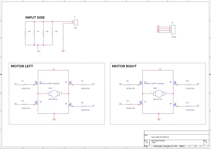
So I prepared a simple H-bridge setup that utilizes four N-channel MOSFETs connected in an H configuration for controlling each motor. Two motors are used, so two H-bridges were made with 8 FETs.
This setup is just a base for the upcoming robot project. This article is about how this Dual Motor Driver Base works and how it's prepared step by step, so let's get started.
Material Required
Following are the materials used in this built-
- AO3400 N channel Mosfet SOT23 Package
- Custom PCB
- 10K resistors 0603 Package
- 2R 1206 package
- JST connectors
- Vertical Header pin male connector
- Micro gear motor
- 3D printed Motor Holder
Mechanical Design for Robot's Base PCB


I first prepared a simple double-wheeled robot in fusion360, the whole model was made around the Micro Gear Motor.
I prepared a Base Board of size 95mm x 36.2mm which was later utilized in the PCB Design.
The motor is added to the base by using two Motor Mounts that we 3D Print and later attach with PCB Standoffs to the base body.
PCB DESIGN


For driving motors, we tend to use common drivers like L293D or its higher version the L298N, which are both H-bridge-based motor drivers that have two channels or two motor outputs.
H-bridge is a unique circuit that can switch the polarity of the voltage applied to any load, it's generally used with motors for changing their rotation from backward to forward and can be made out of switches.
Four FETs are connected in such a way that the first two FETs (Q1 and Q2) Drain is connected to the VCC or Power source that will drive the motor.
The sources of Q1 and Q2 are both connected to the positive and negative sides of the motor.
Two more FETs Q3 and Q4 Drain are linked to Q1 and Q2 sources, as well as the motor terminals.
The Q3 and Q4 Sources are linked to GND.
The gates of Q1 and Q4 are connected together, and the gates of Q2 and Q3 are connected together. If we apply a signal to Q1, Q4 will also get activated, and if the signal is applied to Q2, Q3 will get activated.
1 and 0 will be denoted for HIGH and LOW, respectively. We set Gate of Q1 to 1 and Gate of Q2 to 0, and this turns the motor in one direction. If we set Gate of Q1 to 0 and Gate of Q2 to 1, the polarity of the motor changes, and it starts rotating in the opposite direction.
If both Q1 and Q2 are 1, then a short circuit will occur.
There are a total of two H-bridges on the Base Board which is for controlling both motors.
Additionally, I have added four Load Resistors between the Battery Positive and the input of the H-Bridge. this will limit the current going into the motors.
There's also a CON4 header pin that separates the gates of both H-bridges so we can connect them to a microcontroller to drive the motors.
After finalizing the schematic, PCB was prepared by following the outline provided by the mechanical design of the robot.
PCBWAY


After preparing the PCB and exporting the Gerber data, we sent it to PCBWAY for samples and placed an order for a white solder mask with a black silkscreen.
I received PCBs within a week, and they were excellent, as expected.
White PCBs look great with black silkscreen in general.
I love the quality of PCBs made by PCBWAY. There are other manufacturers available, but their service is always on another level.
check out PCBWay service for getting great PCB service at less cost.
PCB ASSEMBLY
PCB Assy consists primarily of four processes, which are as follows:
- Solder Paste Dispensing Process
- Pick and Place Process
- Hotplate Reflow
- THT Components
Solder Paste Dispensing


The first step is to apply solder paste to each component pad.
We use regular Sn-Pb solder paste that has a melting temperature of 140° to 270°C, and to apply the solder paste, a solder paste syringe with a wide nozzle is used.
Pick and Place Process


We then used an ESD tweaker to carefully pick and place all the SMD components in their assigned places one by one, which took like 30 seconds tops, but the result was a perfect PCB with all the components placed in their locations.
Hotplate Reflow Process


After the "pick and place process, " we carefully lifted the whole circuit board and placed it on my new Mini Hotplate.
The hotplate heats the PCB from below up to the solder paste melting temperature. As a result, the solder paste melts and components get solder on their pads.
THT Components


Next, we add header pins to this board: vertical male header pins for connecting this setup with an Arduino board for testing, JST connectors for connecting two motors to Fets, and one for adding a 3.7V Li-ion Cell.
Adding Motors

After adding THT components to the board, we connect both motors with the JST connectors.
I already soldered male JST wire harnesses to both motors, so we can easily add them to the base PCB without doing any soldering work. this makes assembly a lot easy.
Motor Holder


Next, to hold motors in their place, we add 3D Printed Motor Holders with help of four M3 Screws, these screws will later be replaced by PCB Standoffs for adding a second layer to this base. the second layer will contain the Microcontroller setup which is yet to be finalized.
Adding wheels


I have purchased small wheels for micro motors that were used in a previous project which was this- https://www.hackster.io/Arnov_Sharma_makes/micro-fighter-bot-with-bluetooth-911e33
I repurposed those wheels and use them in this design.
These are regular plastic rims that have a rubber wheel which is great for gripping the surface and running smoothly without oversteering that happens a lot if the wheel is made from completely plastic material.
Arduino Setup

As for the current setup, we need to add an external microcontroller for testing the board.
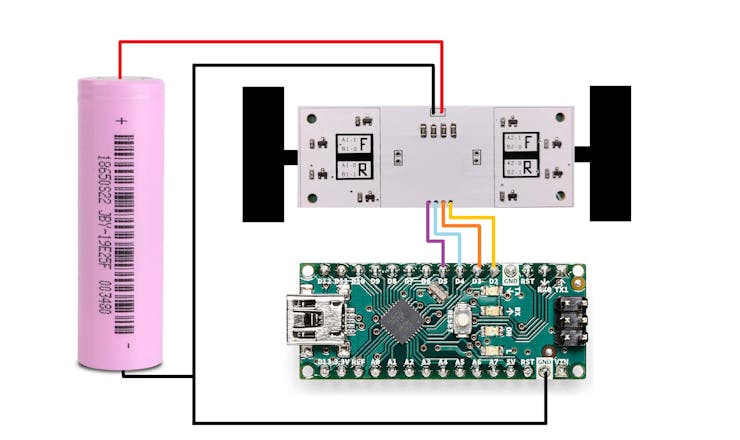
I used an Arduino nano for controlling the gates of MOSFETs.
D2, D3, D4, and D5 I/O pins were connected with the FETs gate along with an additional GND Pin which is connected with the GND of Arduino.
Power to the Motor driver was provided by a single Li-ion cell which was connected to the Baseboard through a JST wire harness.
TEST SKETCH


Here's the code, and it's a simple one.
int in1 = 2;
int in2 = 3;
int in3 = 4;
int in4 = 5;

void setup() {

 pinMode(in1, OUTPUT);
 pinMode(in2, OUTPUT);
 pinMode(in3, OUTPUT);
 pinMode(in4, OUTPUT);

}

void demoOne() {
 digitalWrite(in1, HIGH);
 digitalWrite(in2, LOW);
 digitalWrite(in3, HIGH);
 digitalWrite(in4, LOW);
 delay(2000);

 digitalWrite(in1, LOW);
 digitalWrite(in2, LOW);
 digitalWrite(in3, LOW);
 digitalWrite(in4, LOW);
 delay(2000);

 digitalWrite(in1, LOW);
 digitalWrite(in2, HIGH);
 digitalWrite(in3, LOW);
 digitalWrite(in4, HIGH);
 delay(2000);

 digitalWrite(in1, LOW);
 digitalWrite(in2, LOW);
 digitalWrite(in3, LOW);
 digitalWrite(in4, LOW);
 delay(2000);

}

void loop()
{
  demoOne();

}
We upload the above sketch into the Arduino Nano, and the H-bridge works.
I already tested this setup before and prepared an article about this which you can check out here-
https://www.hackster.io/Arnov_Sharma_makes/h-bridge-for-micro-motors-c27056
The previous version was totally makeshift so I prepared this dual H-Bridge PCB which I will next use in the robot project.
This approach of making something and then improving it from time to time is what makes engineering so much fun and interesting.
What's Next?


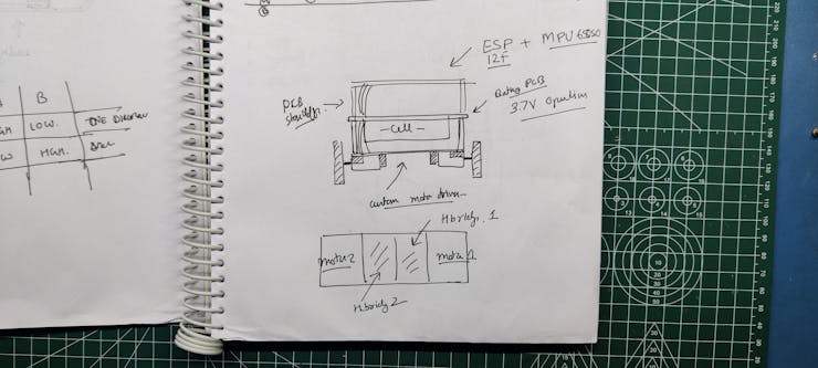
The second part or level of this project is to make a microcontroller layer that will have an MCU connected on the top side and a Li-ion cell holder on the bottom side.
There will also be an MPU6050 sensor for obtaining accelerometer readings so that this robot can stand still on two wheels.
I already made a similar self-balancing robot in the past and will be using slightly modified code from that project in this bot.
This is it for today folks. Stay tuned for the next version.
Special thanks to PCBWAY for supporting this project; do check them out for great PCB service at a lower cost.
Thanks again, and I will be back with a new project soon.
int in1 = 2;
int in2 = 3;
int in3 = 4;
int in4 = 5;

void setup() {

 pinMode(in1, OUTPUT);
 pinMode(in2, OUTPUT);
 pinMode(in3, OUTPUT);
 pinMode(in4, OUTPUT);

}

void demoOne() {
 digitalWrite(in1, HIGH);
 digitalWrite(in2, LOW);
 digitalWrite(in3, HIGH);
 digitalWrite(in4, LOW);
 delay(2000);

 digitalWrite(in1, LOW);
 digitalWrite(in2, LOW);
 digitalWrite(in3, LOW);
 digitalWrite(in4, LOW);
 delay(2000);

 digitalWrite(in1, LOW);
 digitalWrite(in2, HIGH);
 digitalWrite(in3, LOW);
 digitalWrite(in4, HIGH);
 delay(2000);

 digitalWrite(in1, LOW);
 digitalWrite(in2, LOW);
 digitalWrite(in3, LOW);
 digitalWrite(in4, LOW);
 delay(2000);

}

void loop()
{
  demoOne();

}
Dual Motor Driver as Robot Base
*PCBWay community is a sharing platform. We are not responsible for any design issues and parameter issues (board thickness, surface finish, etc.) you choose.
- Comments(0)
- Likes(1)
-
 Engineer
Sep 05,2024
- 0 USER VOTES
- YOUR VOTE 0.00 0.00
- 1
- 2
- 3
- 4
- 5
- 6
- 7
- 8
- 9
- 10
- 1
- 2
- 3
- 4
- 5
- 6
- 7
- 8
- 9
- 10
- 1
- 2
- 3
- 4
- 5
- 6
- 7
- 8
- 9
- 10
- 1
- 2
- 3
- 4
- 5
- 6
- 7
- 8
- 9
- 10
 More by Arnov Arnov sharma
-
 Pocket SNES
Greetings everyone, and welcome back! Today, I’ve got something fun and tiny to share—the Pocket SNE...
-
 Batocera Arcade Box
Greetings everyone and welcome back, Here's something. Fun and nostalgic. Right now, we are using ou...
-
 64x32 Matrix Panel Setup with PICO 2
Greetings everyone and welcome back.So here's something fun and useful: a Raspberry Pi Pico 2-powere...
-
 Portable Air Quality Meter
Hello everyone, and welcome back! Today, I have something incredibly useful for you—a Portable Air Q...
-
 WALKPi PCB Version
Greetings everyone and welcome back, This is the WalkPi, a homebrew audio player that plays music fr...
-
 Delete Button XL
Greetings everyone and welcome back, and here's something fun and useful.In essence, the Delete Butt...
-
 Arduino Retro Game Controller
Greetings everyone and welcome back. Here's something fun.The Arduino Retro Game Controller was buil...
-
 Super Power Buck Converter
Greetings everyone and welcome back!Here's something powerful, The SUPER POWER BUCK CONVERTER BOARD ...
-
 Pocket Temp Meter
Greetings and welcome back.So here's something portable and useful: the Pocket TEMP Meter project.As...
-
 Pico Powered DC Fan Driver
Hello everyone and welcome back.So here's something cool: a 5V to 12V DC motor driver based around a...
-
 Mini Solar Light Project with a Twist
Greetings.This is the Cube Light, a Small and compact cube-shaped emergency solar light that boasts ...
-
 PALPi V5 Handheld Retro Game Console
Hey, Guys what's up?So this is PALPi which is a Raspberry Pi Zero W Based Handheld Retro Game Consol...
-
 DIY Thermometer with TTGO T Display and DS18B20
Greetings.So this is the DIY Thermometer made entirely from scratch using a TTGO T display board and...
-
 Motion Trigger Circuit with and without Microcontroller
GreetingsHere's a tutorial on how to use an HC-SR505 PIR Module with and without a microcontroller t...
-
 Motor Driver Board Atmega328PU and HC01
Hey, what's up folks here's something super cool and useful if you're making a basic Robot Setup, A ...
-
 Power Block
Hey Everyone what's up!So this is Power block, a DIY UPS that can be used to power a bunch of 5V Ope...
-
 Goku PCB Badge V2
Hey everyone what's up!So here's something SUPER cool, A PCB Board themed after Goku from Dragon Bal...
-
 RGB Mixinator V2
Hey Everyone how you doin!So here's a fun little project that utilizes an Arduino Nano, THE MIXINATO...
-
-
AEL-2011 Power Supply Module
545 0 2 -
AEL-2011 50W Power Amplifier
505 0 2 -
-
-
Custom Mechanical Keyboard
706 0 0 -
Tester for Touch Screen Digitizer without using microcontroller
337 2 2 -
Audio reactive glow LED wristband/bracelet with NFC / RFID-Tags
317 0 1 -
-
-


