FRC sensor breakout for NI RoboRIO
I designed this for FRC team 1425 Error Code Xero after a 2019 season marred by repeated electrical connection problems at the RoboRIO and the MXP expansion connector on our Nav-X board. We looked at the board made by Swyft Robotics and decided that it was a great idea but (1) it didn't break out the digital I/Os on the MXP connector and (2) the JST PH connectors required either crimping to very small terminals or wire-to-wire splices to pre-terminated connectors.
Our first version of this board had 4.2mm connectors (Molex Mini-Fit Jr.). We used it for Bunnybots and decided that the connectors were reliable, but terminating the cables was still a problem.
This second version of the board uses 3.81mm pitch Euroblock-style pluggable connectors. They're more expensive than the other options but give you a wide range of screw-clamp, spring-clamp and lever-clamp plugs. The board uses 6-position connectors for the DIO lines with two channels per connector. You can use a single 6-position plug to connect to both channels (e.g. for an encoder) or individual 3-position side-stackable plugs for each channel.
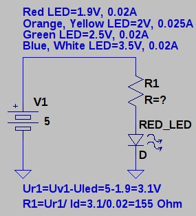
The board has positions for 0805 surface-mount LEDs and resistors on the DIO lines and the relay output channels. The LEDs on the DIO lines are connected so the LED goes ON when the connection goes LOW. Many of the sensors we use are equipped with open-collector/open-drain outputs or can be wired as a switch-closure to ground. With your robot powered on but disabled, you can spin the wheels and verify that both encoder channels are hooked up and that the proximity sensor is working. If the wire's broken, the LEDs don't light up.
The LEDs on the relay outputs are connected so that the LED goes ON when the RoboRIO drives the output HIGH. The LED's are a passive circuit and don't interfere with the RoboRIO's control of the relay but it's not just wiring and may not be acceptable in FRC competition. We'll try to get a rules clarification on this issue. For now, just leave those LEDs off the board.
We've purchased bare boards from PCBWay and assembled them ourselves and we've used PCBWay's assembly service to install the surface-mount resistors and LEDs. We haven't used PCBWay's assembly service for the through-hole connectors; our students are happy to do that themselves.
FRC sensor breakout for NI RoboRIO
*PCBWay community is a sharing platform. We are not responsible for any design issues and parameter issues (board thickness, surface finish, etc.) you choose.

ESP32-S3 1.91inch AMOLED Display Development Board, 240×536, 32-bit LX7 Dual-core Processor, Up to 240MHz Frequency, Accelerometer And Gyroscope Sensor, ESP32 With Display
BUY NOW
ESP32-S3 4.3inch Capacitive Touch Display Development Board, 800×480, 5-point Touch, 32-bit LX7 Dual-core Processor
BUY NOW
ESP32-S3 1.91inch AMOLED Display Development Board, 240×536, 32-bit LX7 Dual-core Processor, Up to 240MHz Frequency, Accelerometer And Gyroscope Sensor, ESP32 With Display
BUY NOW- Comments(0)
- Likes(1)
 Log in to post comments.
-
 Boris
Nov 02,2023
- 0 USER VOTES
- YOUR VOTE 0.00 0.00
- 1
- 2
- 3
- 4
- 5
- 6
- 7
- 8
- 9
- 10
- 1
- 2
- 3
- 4
- 5
- 6
- 7
- 8
- 9
- 10
- 1
- 2
- 3
- 4
- 5
- 6
- 7
- 8
- 9
- 10
- 1
- 2
- 3
- 4
- 5
- 6
- 7
- 8
- 9
- 10
 More by Stephen Tarr
-
-
-
Dvorak 2024 and 'Ye Olde Qwerty' Human-Factored Compact Two-Hand Keyboards
64 0 0 -
-


