Necroware's MCE Adapter
GITHUB: https://github.com/necroware/mce-adapter
The MCA-Adapter is a device, which can convert MDA (and Hercules), EGA and CGA to analogue RGBS signal. It supports following features.
Converts digital MDA, Hercules, CGA, low-res EGA, high-res EGA to analog RGBS or RGBHV/VGA signal
Color DAC for 3, 4, 16 and 64 color modes
Switchable composite sync from H- and V-Sync
Loop through HV-Sync, colors conversion only mode
Switchable composite sync inversion
Includes IBM's "brown-hack"for CGA and 16-colors EGA modes
Switchable green and white monochrome screen emulation
Youtube Videos:
Part 1: Why GBS-8200 is not a CGA/EGA converter https://youtu.be/7c3yLX52ZEs
Part 2: Theory and implementation https://youtu.be/aUFKB4b5KpE
Part 3: Showtime https://youtu.be/F1685u-QQ0k
Why did I make this?
Because why not? I wanted to get some practice with EDA and I needed such an adapter to test some of my old graphics cards.
Why might somebody need this?
If you want to connect your old PC with MDA, CGA or EGA graphics to a more modern VGA display, it's going to be difficult. First of all, this old graphics standards are digital, so RGB information is sent as a bunch of 1 and 0. VGA on the other hand understands only analogue signals, so f.e. the intensity of the red color is defined by some value between two voltages and not by a discrete value. So the first job of this adapter is to translates digital video signals into analogue video signals. However, this is may be not enough, since the horizontal sync signal of the old video standards is not supported by a usual VGA monitor. For this purpose, a very famous upscaler named GBS-8200 and compatible can be used to convert the sync signal to VGA compatible level. However, GBS-8200 expects such called composite sync signal, where horizontal and vertical sync signals are combined. This is, where this adapter comes into place, it doesn't only convert digital RGB signal to analogue, but also composite sync signal from incoming horizontal and vertical signals. Long story short, you will need this adapter to connect a MDA, CGA or EGA graphics card to an analogue RGB monitor, either by using GBS-8200 converter or the adapter standalone, in case your monitor supports horizontal frequencies down to 15kHz.
Why didn't I take an existing solution?
Well, first of all, I wanted to gain some experience in this. Second, I actually was heavily inspired by a YouTube video by TheRasteri, where he evaluates the output possibilities of an old PC, talks about the technical background and creates his own adapter. You can see the video here:
Part 1: https://www.youtube.com/watch?v=kHhpTq-WSJk
Part 2: https://www.youtube.com/watch?v=vwKA1z8tg1g
As I saw his solution with a ROM, I instantly thought, that the same thing can be done using a programmable logic IC, like GAL16V8. It would have some benefits in timing behaviour over a solution with ROM and be also very flexible. So, here it is.
Which modes does it support?
The adapter can convert MDA, Hercules, CGA, 16 colors EGA and 64 colors EGA to standard VGA (RGBHV) or RGBS (combined HV-sync). The sync output frequency is always the same as the input frequency. The adapter can only compose HV-sync, but doesn't actively change it. The digital color signal is converted to analogue color signal, so any analogue RGB monitor should understand it.
Jumpers and switches
Basic jumper description:
J1 mono (jumper off) or color (jumper on)
J2 mode select (depends on the color or mono mode)
J3 invert composite sync signal (see composite signal)
J4 composite sync (1-2) or HV-sync (2-3)
Mode selection:
ModeJ1J2J3MDA/Hercules white (18kHz)OFFOFFONMDA/Hercules green (18kHz)OFFONONCGA/EGA 16 colors (15kHz)ONOFFOFFEGA 64 color (21kHz)ONONON
Composite sync signal
Every end of line the graphics adapter sends a so called H-Sync or horizontal synchronization signal. Every end of the screen the graphics adapter sends so called V-Sync or vertical synchronization signal. The history of this principle goes many years back to cathode tubes, old TVs and monitors. This signals are used for the retraction of the ray in the monitor, so it knows when to restart to draw the next line or the whole screen. The history and the theory behind it is quite long and is not the point here. Important to understand is that different video modes, MDA, CGA, EGA are using different V- and H-Sync frequencies. It is important for the monitor to be able to distinguish them and it does by the frequency of the sync signals, but also by a polarity of the signals. Sometimes one of the sync signals is high positive and sometimes it is low positive. This also helps the monitor to detect it properly, but some monitors don't take it into account and in such cases the Jumper J3 can be helpful. If you have problems with the sync signal with one of the modes try to flip this jumper to get the sync signal inverted. This jumper has however no meaning, if you set the adapter to HV-sync mode (Jumper J4 to 2-3). Here is the overview of the different video modes, their sync frequencies and sync polarities:
Video ModeH-SyncV-SyncMDA+ 18kHz- 50HzCGA+ 15kHz+ 60HzEGA low+ 15kHz+ 60HzEGA high+ 21kHz- 60Hz
Usually, you only need to invert the composite sync signal only if V-Sync signal is negative. In the columns H- and V-Sync + means high-positive and - means low-positive sync signal. EGA exists in two variants low resolution of up to 640x200 and high resolution with up to 720x350, hence the higher H-Sync frequency of 21kHz, since 15kHz are just not enough to draw 350 lines with 60Hz.
How to use this stuff?
Take the gerber files and make a PCB.
Assemble the board
Compile code/mceplug.eqn using EQN2JED tool
Write the compiled jed file to a GAL16V8 IC
Put it into the board and connect the cables f.e. CGA -> MCE Adapter -> GBS-8200 -> Analog RGB Monitor
Bill of materials
Reference#LCSCDescriptionC11C383039electrolythic capacitor 220µFD11C402218diode 1N5819H11C492405pin header 1x6J1231C65114pin header 2x3J41C429954pin header 1x3PWR11C46398USB-B mini portPWR21C152154pin header 1x2 (+5V connector)R1 R2 R33C58592resistor 470 Ohm (or 680 Ohm)R4 R5 R63C58608resistor 330 OhmR71C57438resistor 100 OhmR81C57435resistor 1k OhmU11C6509GAL16V8B (or compatible)VIDEO_IN11C141882DB9 female connector (MDA/EGA/CGA)VIDEO_OUT11C75754DIB15 female connector (VGA)
Tested with following monitors
GBS-8200 with original hardware (only 15kHz modes work)
GBS-8200 with gbs-control firmaware (Hercules and hi-res EGA sync unstable)
NEC Multisync LCD1970NX 19" TFT (everything works fine, Hercules is not in full screen, but works stable)
EIZO L365 15" TFT (only Hi-Res EGA works, doesn't support 15kHz CGA nor 50Hz Hercules)
Necroware's MCE Adapter
*PCBWay community is a sharing platform. We are not responsible for any design issues and parameter issues (board thickness, surface finish, etc.) you choose.
- Comments(2)
- Likes(6)
-
 Engineer
Jan 16,2024
-
 syuu831
Oct 08,2023
-
 Adam Laskowski
Oct 04,2023
-
 Engineer
Jun 12,2023
-
 Tor-Eirik Bakke Lunde
Jun 12,2023
-
 Bryan Gibson
Jun 07,2023
- 0 USER VOTES
- YOUR VOTE 0.00 0.00
- 1
- 2
- 3
- 4
- 5
- 6
- 7
- 8
- 9
- 10
- 1
- 2
- 3
- 4
- 5
- 6
- 7
- 8
- 9
- 10
- 1
- 2
- 3
- 4
- 5
- 6
- 7
- 8
- 9
- 10
- 1
- 2
- 3
- 4
- 5
- 6
- 7
- 8
- 9
- 10
-
 Necroware S7-VRM (2024 Version)
Note from PCBWay: There are some problems in the BOM on the project page that cannot be resolved. If...
-
 Atari 2600 PlusCart
Original Site: https://gitlab.com/firmaplus/atari-2600-pluscart
-
 2 digit Turbo Display
Original GITHUB: https://github.com/wiretap-retro/2-digit-Turbo-Display?tab=readme-ov-file#2-digit-t...
-
 TRH9000 - a graphics expansion cartridge for MSX
Original GITHUB: https://github.com/cristianoag/trh9000
-
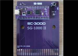 SD-1000 - Sega flash multicart for SC-3000, SG-1000 and Mark III based on Pico Clone
Original GITIHUB: https://github.com/aotta/SD-1000
-
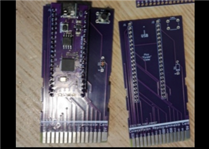 PiCOLECO - a Colecovision flash multicart based on Pico clone
Original GITHUB: https://github.com/aotta/PiCOLECO
-
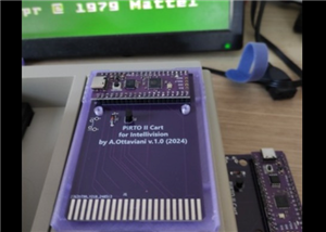 Pi-RTO II - a Intellivision flash multicart based on Pico clone
Original GITHUB: https://github.com/aotta/PiRTOII
-
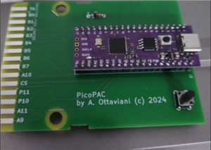 PicoPAC - Flash Multicart for Philips Videopac (Magnavox Odyssey 2)
Original GITHUB: https://github.com/aotta/PicoPACMore info: https://www.nightfallcrew.com/22/09/202...
-
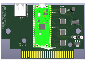 PicoMSX (Pico MSX Not MSXPico)
ORIGINAL GITHUB: https://github.com/Chandler-Kluser/picomsxThis project is on development by his aut...
-
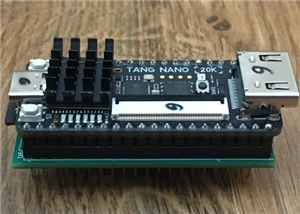 MSX Goauld Rev. 4.1
Original GITHUB: https://github.com/jabadiagm/MSXgoauld_tn20k
-
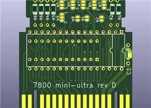 Atari 7800 Mini Ultra Rev. D Game Cart
Please see the AtariAge forum: https://forums.atariage.com/topic/69710-the-7800-cartridge-board-thre...
-
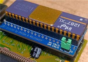 286 Booster from Necroware
Original GITHUB:https://github.com/necroware/287-boosterCredits to Necroware.
-
 MSX SD Mapper v2
ORIGINAL GITHUB: GitHub - fbelavenuto/msxsdmapperv2: MSX SD Mapper Interface V2
-
 Atari 2600 & 7800 Pico Cart Nightfall Version
Original Website: https://www.nightfallcrew.com/17/01/2025/picoa10400-flashcart-for-atari-2600-7800/
-
 Atari XE FULL RA Cart / ECI Extender v2.0
TESTED AND WORKING PERFECT.
-
 Atari 1200XL Extender Cart
Original Website: https://www.bitsofthepast.com/cartridgeboards.html#
-
 Atari 1200XL RA Extender ( Angle Cart )
Original Website: https://www.bitsofthepast.com/cartridgeboards.html#
-
 Atari XE ECI port to XL PBI Angle Cart
Original Creator and Website: https://www.bitsofthepast.com/PBI_ECIBoards.html#ATTENTION: This proje...
-
-
mammoth-3D SLM Voron Toolhead – Manual Drill & Tap Edition
88 0 0 -
-
AEL-2011 Power Supply Module
602 0 2 -
AEL-2011 50W Power Amplifier
542 0 2 -
-
-
Custom Mechanical Keyboard
746 0 0 -
Tester for Touch Screen Digitizer without using microcontroller
371 2 2 -
Audio reactive glow LED wristband/bracelet with NFC / RFID-Tags
346 0 1 -
-


