|
OrCad Cadance |
PCB Candle that glows forever- KINDA
Hey everyone how you doing!
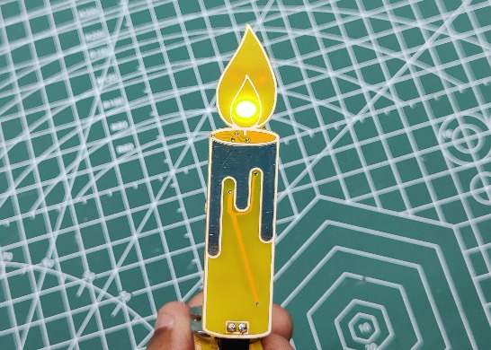
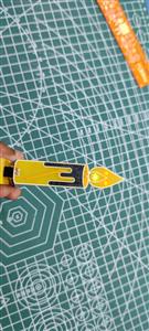
So this is an EVER GLOWING CANDLE PCB that will glow forever and never run out of wax because it's not made out of wax.
However, it will stop glowing after a month of constant blinking when the battery runs out.
The Idea here was to make an awesome and safe night light-decorative light for my desk, Aroma candles, and other decorative candles look great but they are dangerous to keep around, the fire hazard is one of the problems that can cause because of Candles.
To Be honest, this small reason was enough to make an alternative with PCBs because that is what I like, making designs of different stuff from PCBs.
As for the circuit, I utilized a simple FLIP FLOP Circuit that utilizes a couple of BC547 NPN transistors with few resistors and SMD capacitors.
About the working of FLIP FLOP Circuit
_VRw3YcTkl2.gif?auto=compress%2Cformat&gifq=35&w=740&h=555&fit=max)
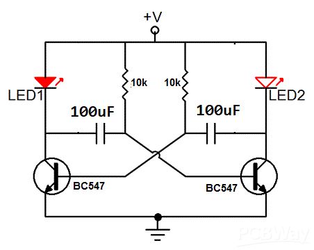
This circuit is a FLIP-FLOP circuit that is designed around a BC547 NPN Transistor that is connected in such a way that the capacitor is connected to the base of the transistor and when it gets charged, the transistor provides a pulse for a short duration to the base of the transistor causes a blink. this process is the same for both LEDs and causes a FLIP-FLOP blinking effect.
Why not use a Microcontroller?
Intead of utilizing the above FLIP-FLOP Circuit, a microcontroller like ATTINY13A or STM8 could be used here as well which could make this setup a lot easier and its code would be much simpler.
The reason was to not rely on MCUs for such a simple task because of two reasons, first one is the global chip shortage which makes these mentioned MCUs hard to get and the second reason is the cost, ATTINY13 cost more than 2$ nowadays, and its lead time is also too long so instead I utilized an OLD but GREAT Method to flash two LEDs.
MATERIAL REQUIRED
Following are the materials used in this built-
- CUSTOM PCB
- LED 0805 Package ORANGE
- LED 0805 Package WHITE
- BC547 transistor SOT23-3 package
- 10K Resistor 0805 Package
- 100uF 16V SMD Capacitor
- CON2 Header pin, Male and female both
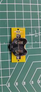
- CR2032 Coin cell and its SMD Holder
- Arduino Nano - for demonstration, you can use any DEV Board
- LEDs 3mm any color
ARDUINO SETUP
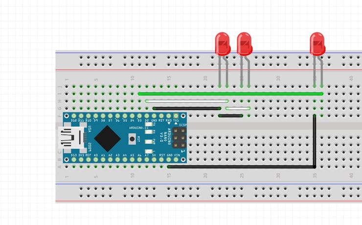
Here's an example of how we can make this same setup with a Microcontroller, An Arduino is being used here but instead of NANO, we can utilize ATTINY MCUs by using the same sketch with a little bit of PIN Number change.
As for wiring, two LEDs are connected to the D2 Pin of the Arduino and one is connected to the D3 of the Arduino.
Here's the code-
int pinsCount=2;                        // declaring the integer variable pinsCount
int pins[] = {2,3};          // declaring the array pins[]
void setup() {
pinMode(2, OUTPUT);
pinMode(3, OUTPUT);
}
void loop() {
for (int i=0; i<pinsCount; i=i+1){    // chasing right
digitalWrite(pins[i], HIGH);         // switching the LED at index i on
delay(70);                          // stopping the program for 100 milliseconds
digitalWrite(pins[i], LOW);          // switching the LED at index i off
}
for (int i=pinsCount-1; i>0; i=i-1){   // chasing left (except the outer leds)
digitalWrite(pins[i], HIGH);         // switching the LED at index i on
delay(70);                          // stopping the program for 100 milliseconds
digitalWrite(pins[i], LOW);          // switching the LED at index i off
}
}
PCB DESIGN



Because this board was themed around a candle, I first searched for a Black and white image of a candle on the internet, after converting the image format into BMP, I imported it into my PCB Cad software and save it as a Silkscreen Top layer.
I designed the schematic and then converted it into a board file.
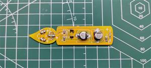
After using the saved candle layout, I added transistors, resistors, and capacitors on the middle section and leds on the flame part.
White LEDs will be placed in the middle and orange LEDs will be placed on Top of the flame.
As for the LED placement, I added LED inverted so their glow will be visible from the front of the PCB.
For this, the soldermask of the TOP Layer is open in the whole flame section, this will let the glow of LED transfer from the Bottom side to the TOP side through the FR4 Board.
FR4 will act as a diffuser in this case.
GETTING PCBS FROM PCBWAY
_1dK60OoLEo.gif?auto=compress%2Cformat&gifq=35&w=740&h=555&fit=max)

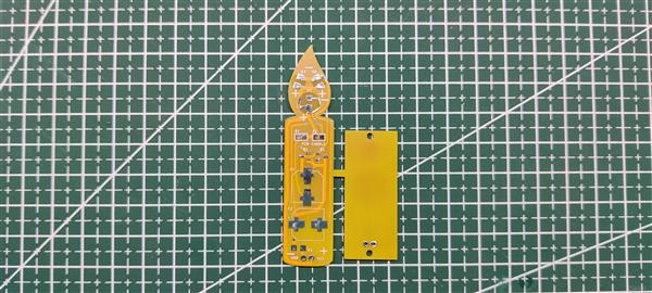
After completing the PCB Design, I exported the Gerber data and send it to PCBWAY for samples.
I choose Yellow Soldermask for this project, Candles are white and I should've chosen a white mask but no worries, I will be ordering Version 2 of this project in a white color mask.
PCBs got delivered in a week which was super fast.
As for the quality of the PCBs, each PCB were made properly and there were no error or misprints anywhere.
Overall quality was super and I recommend you guys for checking them out if you need great PCB service for less cost.
_BAuQB5obfP.gif?auto=compress%2Cformat&gifq=35&w=740&h=555&fit=max)
Also, I designed the PCB in such a way that we can disconnect the Candle PCB with its Coin Cell Holder board by cutting a join in between them by a cutter.
After partitioning the PCB into two separate boards, we prepare for the assembly process.
PCB ASSEMBLY
PCB ASSEMBLY Process contains three major steps which are-
- Solder Paste Dispensing
- PICK and PLACE Process
- HOTPLATE REFLOW Process
SOLDER PASTE DISPENSING
_ETmnODp0UN.gif?auto=compress%2Cformat&gifq=35&w=740&h=555&fit=max)
The first step is to apply solder paste to each component pad. We use Regular Sn-Pb solder paste that has a melting temp of 140 to 270 °C.
PICK AND PLACE PROCESS
_yEXpdQU9Tl.gif?auto=compress%2Cformat&gifq=35&w=740&h=555&fit=max)
I then used an ESD Tweeaser to carefully pick and place each SMD component in its assigned place one by one which took like 30 Seconds tops but the result was a perfect PCB with all the components placed in their location.
LED PLACEMENT
_Xj7NzsrpYH.gif?auto=compress%2Cformat&gifq=35&w=740&h=555&fit=max)
As for the LED Placement, we add them inverted in their pads, because I'm using 0805 package LED and the Pad on PCB is 1206, it can easily hold the inverted LED, just make sure to apply extra solder paste to LED Pads.
HOTPLATE REFLOW PROCESS
_8zeFLGn22y.gif?auto=compress%2Cformat&gifq=35&w=740&h=555&fit=max)
After the "PICK & Place Process", I carefully lifted the whole circuit board and place it on my DIY SMT Hotplate which is also homemade just like this project.
After a few mins when the hotplate reaches the Solderpaste melting TEMP, all the components will get soldered by this Hot Reflow process.
BASE COIN CELL HOLDER PCB
_hQS6QHVXpM.gif?auto=compress%2Cformat&gifq=35&w=740&h=555&fit=max)
- After completing the Candle PCB, we make the Coin cell Board by first adding solder paste to all three pads of the coin cell holder board.
- next, we place the SMD Coin Cell Holder in its assigned place and reflow the whole board.
- After reflow, we add the CON2 Female Header Pin on the board by using a soldering iron.
This board will be the main power source of the candle.
ADDING CON2 PORT
_P3I1ELcOZQ.gif?auto=compress%2Cformat&gifq=35&w=740&h=555&fit=max)
After the Hotplate reflow process, we check the Candle board visually and then add a Vertical CON2 Male header pin to the Candle board by using a soldering Iron.
This CON2 port will let us attach this PCB on a breadboard for power or on its Coin Cell board.
RESULT
_1wd8yt6UXJ.gif?auto=compress%2Cformat&gifq=35&w=740&h=555&fit=max)
Here's the result and as you can see, this setup is blinking and is working properly.
Version 2 will be much bigger and will feature more LEDs and possibly a much better Blinking circuit.
Till then, stay tuned. Special thanks to PCBWAY for supporting this project, do check them out for getting great PCB Service for less cost.
Peace out
int pinsCount=2; // declaring the integer variable pinsCount
int pins[] = {2,3}; // declaring the array pins[]
void setup() {
pinMode(2, OUTPUT);
pinMode(3, OUTPUT);
}
void loop() {
for (int i=0; i<pinsCount; i=i+1){ // chasing right
digitalWrite(pins[i], HIGH); // switching the LED at index i on
delay(70); // stopping the program for 100 milliseconds
digitalWrite(pins[i], LOW); // switching the LED at index i off
}
for (int i=pinsCount-1; i>0; i=i-1){ // chasing left (except the outer leds)
digitalWrite(pins[i], HIGH); // switching the LED at index i on
delay(70); // stopping the program for 100 milliseconds
digitalWrite(pins[i], LOW); // switching the LED at index i off
}
}
PCB Candle that glows forever- KINDA
*PCBWay community is a sharing platform. We are not responsible for any design issues and parameter issues (board thickness, surface finish, etc.) you choose.
- Comments(0)
- Likes(2)
-
 bec 6z
Oct 02,2025
-
 IObrizio Fabrizio
Nov 11,2022
- 0 USER VOTES
- YOUR VOTE 0.00 0.00
- 1
- 2
- 3
- 4
- 5
- 6
- 7
- 8
- 9
- 10
- 1
- 2
- 3
- 4
- 5
- 6
- 7
- 8
- 9
- 10
- 1
- 2
- 3
- 4
- 5
- 6
- 7
- 8
- 9
- 10
- 1
- 2
- 3
- 4
- 5
- 6
- 7
- 8
- 9
- 10
 More by Arnov Arnov sharma
-
 Pocket SNES
Greetings everyone, and welcome back! Today, I’ve got something fun and tiny to share—the Pocket SNE...
-
 Batocera Arcade Box
Greetings everyone and welcome back, Here's something. Fun and nostalgic. Right now, we are using ou...
-
 64x32 Matrix Panel Setup with PICO 2
Greetings everyone and welcome back.So here's something fun and useful: a Raspberry Pi Pico 2-powere...
-
 Portable Air Quality Meter
Hello everyone, and welcome back! Today, I have something incredibly useful for you—a Portable Air Q...
-
 WALKPi PCB Version
Greetings everyone and welcome back, This is the WalkPi, a homebrew audio player that plays music fr...
-
 Delete Button XL
Greetings everyone and welcome back, and here's something fun and useful.In essence, the Delete Butt...
-
 Arduino Retro Game Controller
Greetings everyone and welcome back. Here's something fun.The Arduino Retro Game Controller was buil...
-
 Super Power Buck Converter
Greetings everyone and welcome back!Here's something powerful, The SUPER POWER BUCK CONVERTER BOARD ...
-
 Pocket Temp Meter
Greetings and welcome back.So here's something portable and useful: the Pocket TEMP Meter project.As...
-
 Pico Powered DC Fan Driver
Hello everyone and welcome back.So here's something cool: a 5V to 12V DC motor driver based around a...
-
 Mini Solar Light Project with a Twist
Greetings.This is the Cube Light, a Small and compact cube-shaped emergency solar light that boasts ...
-
 PALPi V5 Handheld Retro Game Console
Hey, Guys what's up?So this is PALPi which is a Raspberry Pi Zero W Based Handheld Retro Game Consol...
-
 DIY Thermometer with TTGO T Display and DS18B20
Greetings.So this is the DIY Thermometer made entirely from scratch using a TTGO T display board and...
-
 Motion Trigger Circuit with and without Microcontroller
GreetingsHere's a tutorial on how to use an HC-SR505 PIR Module with and without a microcontroller t...
-
 Motor Driver Board Atmega328PU and HC01
Hey, what's up folks here's something super cool and useful if you're making a basic Robot Setup, A ...
-
 Power Block
Hey Everyone what's up!So this is Power block, a DIY UPS that can be used to power a bunch of 5V Ope...
-
 Goku PCB Badge V2
Hey everyone what's up!So here's something SUPER cool, A PCB Board themed after Goku from Dragon Bal...
-
 RGB Mixinator V2
Hey Everyone how you doin!So here's a fun little project that utilizes an Arduino Nano, THE MIXINATO...
-
-
mammoth-3D SLM Voron Toolhead – Manual Drill & Tap Edition
207 0 0 -
-
AEL-2011 Power Supply Module
730 0 2 -
AEL-2011 50W Power Amplifier
607 0 2 -
-
-
Custom Mechanical Keyboard
812 0 0 -
Tester for Touch Screen Digitizer without using microcontroller
438 2 2 -
Audio reactive glow LED wristband/bracelet with NFC / RFID-Tags
391 0 1 -
-


