RF keying relay
A simple RF switch .
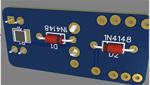
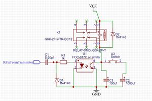
Tap RF from the transmitters antenna and control a linear amplifier or similar,
older amplifiers have voltages and current draws that may damage newer transceivers, this board will isolate
the two from each other. It can be used with or without the relay depending on the amplifier, but the relay
will always give full isolation, it just means you have to supply VCC for the relay, the circuit switches the Negative .
This can be fitted inside the amp or in a suitable box on the cable .
as well as using RF to do the switching , if C1 is swapped for a diode (or shorted out), i would use a diode! -
you can do the switching with 12v+ also.
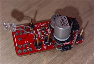
i have added a picture of a prototype board with a diode added. The LED was just for testing. The first board i did ,
the relay was not polarised but i corrected this now.
Also note the silkscreen markings for the capacitors are for tantalum SMD caps so be ware the markings are at the
positive end (who knows why they marked smd caps opposite). So if you use electrolytic caps they look as though
they are backwards.
Please if you use this make sure you are satisfied with the operation before you connect it up to your equipment.
It's a project No Guarantee's!
RF keying relay
*PCBWay community is a sharing platform. We are not responsible for any design issues and parameter issues (board thickness, surface finish, etc.) you choose.
- Comments(0)
- Likes(2)
-
 Dominik Wodzick
Dec 12,2024
-
 Engineer
Oct 01,2024
- 0 USER VOTES
- YOUR VOTE 0.00 0.00
- 1
- 2
- 3
- 4
- 5
- 6
- 7
- 8
- 9
- 10
- 1
- 2
- 3
- 4
- 5
- 6
- 7
- 8
- 9
- 10
- 1
- 2
- 3
- 4
- 5
- 6
- 7
- 8
- 9
- 10
- 1
- 2
- 3
- 4
- 5
- 6
- 7
- 8
- 9
- 10
 More by Colin Wise
-
-
mammoth-3D SLM Voron Toolhead – Manual Drill & Tap Edition
140 0 0 -
-
AEL-2011 Power Supply Module
655 0 2 -
AEL-2011 50W Power Amplifier
567 0 2 -
-
-
Custom Mechanical Keyboard
769 0 0 -
Tester for Touch Screen Digitizer without using microcontroller
395 2 2 -
Audio reactive glow LED wristband/bracelet with NFC / RFID-Tags
364 0 1 -
-


