|
Autodesk Fusion 360Autodesk
|
SOLAR Bank!
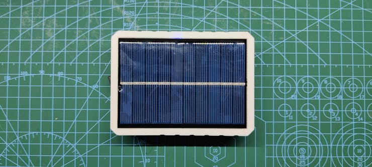
This is the SOLAR BANK which is essentially a power bank that has a solar panel inbuilt.

This solar panel is capable of providing 5V 250mA which can be used to charge a Li-ion cell. we can then use this Li-ion cell to power something big like an Arduino for example.

My goal was to make a Power source for powering my Previous Arduino project with some solar twist. The twist here would be a self-sufficient power source capable of charging itself without using wall adaptors.
Now the working of this Solar bank is super simple, I used a 3.7V 2200mAh Li-ion Cell which is connected to a Boost module that is based around IP5306.
This IP5306 is a power management IC that boosts 3.7V into 5V 2A.

I added this module in a custom 3D printed the enclosure and made a super handy power bank that is capable of providing 5V to any Arduino-like board.
This article is gonna be about the whole building process of this Solar Power Bank so let's get started!
Material Required
I used the following things in this build-
- Solar Panel 5V/200mA (got from PCBWAY Giftshop)
- IP5306 BOOST MODULE
- Rocker Switch
- 10mm LED
- DC jack
- 3D Printed Enclosure - Body and Lid
SOLAR PANEL Working


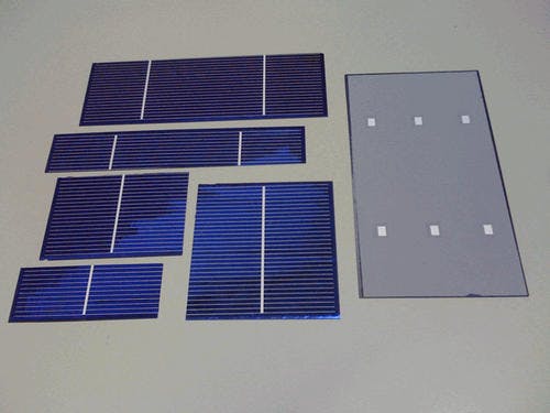
Solar Panels are basically a cluster of photovoltaic cells that convert the sun’s energy into electricity.
These photovoltaic cells each convert the sun's energy into electric energy, but each cell can outputs from 0.4V to 1V depending on the type and we can get desirable current by reducing its size.
As for its working principle, Photovoltaic cells are sandwiched between layers of semiconducting materials such as silicon. Each layer has different electronic properties that energize when hit by photons from sunlight, creating an electric field.
This is known as the photoelectric effect – and it’s this that creates the current needed to produce electricity.
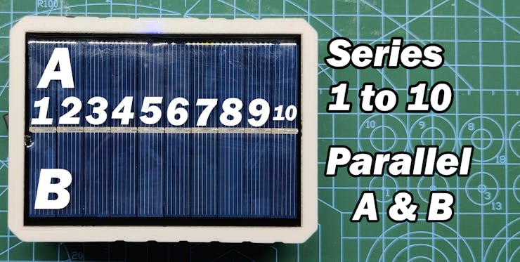
To get 5V, these cells are connected in series and then in parallel for getting a decent current.
Do check out this amazing article about the in-depth working of solar cells.
https://circuitglobe.com/photovoltaic-or-solar-cell.html
Getting the right Solar Panel


As for the Solar Panel that I'm using in this build, I got this panel from PCBWAY's Giftshop that you guys can check out.
Their Giftshop contains all the major components that include dev boards, different kinds of sensors, and even stuff like the solar panel module that I'm using.

The Module that I'm using has 10 solar cells connected in series so I'm guessing each can output 0.5V, then this line is in parallel with another 10 cells so that would mean each line is of 5V 100mA so two lines would make 5V 200mA.
Boost module - IP5306

What exactly are Boost Modules? and where we should use one.
A Boost Module is basically a circuit that increases the voltage fed to it through its input side and outputs an increased voltage which is being boosted by an onboard inductor, a semiconductor switch, capacitor, and a diode.
We need to use Boost modules in situations where the source is 3.3V but we need to feed the device 5V.
By using a Boost module, we can easily step up this 3.3V into 5V so the device can run without any issue.
Here's a wonderful article written on this topic which you can check out to know more about the working of the boost module. https://components101.com/articles/boost-converter-basics-working-design
What I'm gonna use is a powerful Boost module circuit which is based around IP5306 which is a Power Management IC generally used in Powerbanks and mobile devices.

IP5306 is a fully-integrated multi-function power management that comes in the SoC package.
It has an internal Boost Converter setup along with a proper Li-ion Battery charge management setup that has a low discharge and high charge cut feature which is a must-have function when working with Li-ion cells.
Li-ion cells are dangerous if overcharged so we generally use a BMS Module to cut off its voltage when attached to any charging source, IP5306 has this function which means we dont have to attach any Battery protection setup with it.
Also, we get battery status LED Indication feature.
It can boost the Voltage of any cell from 2.8V ~ 3.7V to 5V 2A.
checkout its datasheet from here- http://www.injoinic.com/wwwroot/uploads/files/20200221/0405f23c247a34d3990ae100c8b20a27.pdf
I found this IC's USB Module online and implemented it into my project.
Wiring of the whole setup


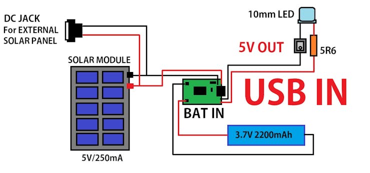
By following the above wiring diagram, I made the connection between the IP5306 Module battery and the Solar panel.
I connected the Solar panel's positive and negative to the Micro USB Port's positive and negative as solar panel in an input power source that will feed voltage into the system for charging application.
Then I added a Li-ion cell with its assigned pads.
After doing the basic wiring, I took this Setup outside for testing the voltage and current status of the whole system.
Testing


For testing this setup, we need to put it under bright sunlight and first check its voltage which should be between 4.5V to 5V.
LED of IP5306 LED should start blinking which shows that the battery is now charging.
Li-ion cells usually require 4.2V in order to get fully charged, if we are getting 4.5V or 5V it's okay because the IP5306 has an internal HIGH Cut feature that cuts the input power of the system as the voltage reaches the 4.2V threshold.

Then after measuring the voltage, we measure the current which should be between 200mA to 100mA depending on the battery voltage, Lithium cells tend to draw more current when their voltage lies between 2.2 to 3.1V, after crossing that limit, the current gradually decreases.
After testing if the solar cell is working, we move on to the next process which is the final assembly with the custom 3D Printed body and 10mm LED.
3D Printed Body


I prepared a rectangular body that houses the solar panel on one side and contains all the major electronics inside.
I used fusion360 to model the whole strictly and then 3D printed the body and its lid with my ender 3 by using the following print setting.
Nozzle Dia- 0.8mm
Infill- 20%
Layer height- 0.3mm
Support - YES
Also, if you dont own a 3D printer, you can check out PCBWAY's 3D Printing service.


Before starting the Final assembly, I took the 3D Printed body and glued the panel on the outside, I used regular hot glue for this step and let the glue dry for a few mins.
Final Assembly


the main assembly which includes the following steps.
- We first add a Lithium Cell to the main Body by using Hot glue to secure it completely in its place.
- We do the same with the boost module.
- Then we add a 10mm LED in its place by using Hot glue.
- After that, we add Rocker Switch in its assigned place.
- Then we add a DC Barrel jack which will be connected in parallel to the solar panel output. (goal for adding this barrel jack is, we can connect an external panel with this setup as well for charging the cell)
- Then we do all the connections which are shown in the Above wiring diagram
- In the end, we tightened its lid with four M2 screws, and the assembly is completed.
Result and Conclusion


This was the overall result, a working handheld solar-powered 5V power source that is capable of running major Arduino projects.
We just plug any USB in it and power the device, it can even charge a smartphone, up to 2200mAh ( less than that because some power will be lost as nothing is 100% efficient)
During Nighttime or when the sun is not available, we can use its onboard micro USB Port to charge the setup.
Features


- Super Small and handy, can power any Arduino or Development board through USB Port.
- Backup time of Lithium Cell - Depends on how much current we are drawing, we get 3 Hours + if we draw 5V at 0.500A.
- USB output has an auto turn ON and Turn OFF feature when we plug any USB Device, Circuit starts itself and provides constant 5V. when we plug off the USB Device, the circuit stays ON for a few seconds and then shuts itself down.
- Micro USB Port for charging the setup via USB Cable and smartphone charger.
- Side Blue Light has a Backup of 24 Hours +
- An Additional DC Jack has been added to this setup for connecting an external solar panel module, we can connect a bunch of solar modules together and make a solar grid by connecting multiple PCs together.
This is it for today, Leave a comment if you guys need any help, and I'll be back with another project soon!
DO check out PCBWAY to get great PCB Service for less cost!
Peace out!

SOLAR Bank!
- Comments(0)
- Likes(0)
- 0 USER VOTES
- YOUR VOTE 0.00 0.00
- 1
- 2
- 3
- 4
- 5
- 6
- 7
- 8
- 9
- 10
- 1
- 2
- 3
- 4
- 5
- 6
- 7
- 8
- 9
- 10
- 1
- 2
- 3
- 4
- 5
- 6
- 7
- 8
- 9
- 10
- 1
- 2
- 3
- 4
- 5
- 6
- 7
- 8
- 9
- 10
 More by Arnov Arnov sharma
-
 Pocket SNES
Greetings everyone, and welcome back! Today, I’ve got something fun and tiny to share—the Pocket SNE...
-
 Batocera Arcade Box
Greetings everyone and welcome back, Here's something. Fun and nostalgic. Right now, we are using ou...
-
 64x32 Matrix Panel Setup with PICO 2
Greetings everyone and welcome back.So here's something fun and useful: a Raspberry Pi Pico 2-powere...
-
 Portable Air Quality Meter
Hello everyone, and welcome back! Today, I have something incredibly useful for you—a Portable Air Q...
-
 WALKPi PCB Version
Greetings everyone and welcome back, This is the WalkPi, a homebrew audio player that plays music fr...
-
 Delete Button XL
Greetings everyone and welcome back, and here's something fun and useful.In essence, the Delete Butt...
-
 Arduino Retro Game Controller
Greetings everyone and welcome back. Here's something fun.The Arduino Retro Game Controller was buil...
-
 Super Power Buck Converter
Greetings everyone and welcome back!Here's something powerful, The SUPER POWER BUCK CONVERTER BOARD ...
-
 Pocket Temp Meter
Greetings and welcome back.So here's something portable and useful: the Pocket TEMP Meter project.As...
-
 Pico Powered DC Fan Driver
Hello everyone and welcome back.So here's something cool: a 5V to 12V DC motor driver based around a...
-
 Mini Solar Light Project with a Twist
Greetings.This is the Cube Light, a Small and compact cube-shaped emergency solar light that boasts ...
-
 PALPi V5 Handheld Retro Game Console
Hey, Guys what's up?So this is PALPi which is a Raspberry Pi Zero W Based Handheld Retro Game Consol...
-
 DIY Thermometer with TTGO T Display and DS18B20
Greetings.So this is the DIY Thermometer made entirely from scratch using a TTGO T display board and...
-
 Motion Trigger Circuit with and without Microcontroller
GreetingsHere's a tutorial on how to use an HC-SR505 PIR Module with and without a microcontroller t...
-
 Motor Driver Board Atmega328PU and HC01
Hey, what's up folks here's something super cool and useful if you're making a basic Robot Setup, A ...
-
 Power Block
Hey Everyone what's up!So this is Power block, a DIY UPS that can be used to power a bunch of 5V Ope...
-
 Goku PCB Badge V2
Hey everyone what's up!So here's something SUPER cool, A PCB Board themed after Goku from Dragon Bal...
-
 RGB Mixinator V2
Hey Everyone how you doin!So here's a fun little project that utilizes an Arduino Nano, THE MIXINATO...
-
-
mammoth-3D SLM Voron Toolhead – Manual Drill & Tap Edition
176 0 0 -
-
AEL-2011 Power Supply Module
699 0 2 -
AEL-2011 50W Power Amplifier
592 0 2 -
-
-
Custom Mechanical Keyboard
788 0 0 -
Tester for Touch Screen Digitizer without using microcontroller
413 2 2 -
Audio reactive glow LED wristband/bracelet with NFC / RFID-Tags
377 0 1 -
-


