Universal Battery AutoCut Charge Controller with LCD - DIY at Home
Are you looking to build a reliable and efficient battery AutoCut charge controller? Look no further! In this DIY guide, we will walk you through creating a Universal Battery AutoCut Charge Controller with an LCD display using the Atmega328P microcontroller. This project is perfect for both beginners and seasoned electronics enthusiasts. By following this step-by-step tutorial, you can safeguard your batteries from overcharging and deep discharging, ensuring their longevity and optimal performance.
Why Build a Battery AutoCut Charge Controller?
Battery maintenance is crucial for extending the life of your batteries and ensuring their performance. Overcharging can lead to overheating and reduced lifespan, while deep discharging can cause irreversible damage. A battery AutoCut charge controller automatically manages the charging process, cutting off power when the battery is fully charged and reconnecting when the voltage drops below a specified level. This DIY project will save you money and give you the satisfaction of building a functional and practical device.
Components Needed
- Before we dive into the build, let’s gather all the necessary components:
- Atmega328P Microcontroller: The brain of our project, widely used in Arduino projects for its simplicity and performance.
- 16MHz Crystal Oscillator: Provides the clock signal for the microcontroller.
- Voltage Divider (10kΩ & 5.6kΩ Resistors): Used to scale down the battery voltage to a safe level for the microcontroller to read.
- 16x2 LCD Display: To display battery status, voltage, and other information.
- 5V Relay: Acts as a switch to disconnect the battery from the charger when fully charged.
- Diodes, Capacitors, and Resistors: For filtering, protection, and stabilizing the circuit.
- Breadboard and Connecting Wires: For assembling the circuit.
- Power Supply: A 12V battery or equivalent DC source.
- Programming Tools: Arduino IDE, USB to Serial converter (if needed), and a laptop or PC.
- PCB: Custom-designed circuit board to organize and streamline your project.
Circuit Design

Fig: Universal Battery AutoCut Charge Controller with LCD - DIY at Home
The heart of this project is the Atmega328P microcontroller, which monitors the battery voltage using an analog input pin connected through a voltage divider. The 16x2 LCD display is used to show real-time data like battery voltage, charging status, and other important metrics. The 5V relay is controlled by the microcontroller to disconnect the charger when the battery is fully charged and reconnect it when the voltage drops below a preset level.
- Microcontroller Setup: Start by connecting the 16MHz crystal oscillator to the Atmega328P's XTAL1 and XTAL2 pins. This will provide the necessary clock signal for the microcontroller.
- Voltage Sensing: Connect the battery's positive terminal to the voltage divider circuit. The output of the voltage divider is fed into one of the analog input pins (e.g., A0) of the Atmega328P. This allows the microcontroller to monitor the battery voltage in real-time.
- LCD Display: Connect the 16x2 LCD to the microcontroller using the appropriate data and control pins (RS, E, D4-D7). The LCD will display the battery voltage and status updates.
- Relay Control: The 5V relay is connected to one of the digital output pins of the microcontroller. This pin will drive the relay to cut off the charger when the battery is full and re-engage it when the battery needs charging.
- Power Supply: Ensure the microcontroller and other components are powered with a stable 5V supply. You can use a voltage regulator to step down from a higher voltage source if needed.
Circuit Diagram Explanation
This schematic represents the Universal Battery AutoCut Charge Controller designed around the Atmega328P microcontroller. Below is a detailed explanation of the key components and their connections:

https://www.pcbway.com/?from=technology4power
Every electronic device needs PCBs. Are you looking for the Best PCB order? PCBWay is one the best PCB manufacturing companies. Order 10 pcs PCB for only $5. Visit now https://www.pcbway.com/?from=technology4power
1. Power Supply Section
DC Input (DC1): The circuit is powered by a DC supply connected at DC1. The input voltage is fed into the voltage regulator.
Voltage Regulator (U2 - L7805ABV): This 5V regulator ensures that a stable 5V is supplied to the microcontroller and other components. It’s connected with capacitors C1 and C2 for filtering the input and output voltages to reduce noise.
USB-B Connector (H8): Provides an alternative power input method through a USB cable, which also supplies 5V to the system.
2. Microcontroller Section
Atmega328P (U1): This is the brain of the circuit, controlling all functions. The microcontroller runs on a 16MHz crystal oscillator (X1), with capacitors C5 and C6 stabilizing the oscillation.
Pins Setup:
Analog Inputs (A0-A5): These pins are used to read analog signals, like battery voltage.
Digital I/O (PD0-PD7, PB0-PB7, PC0-PC5): These pins are configured for various control and communication tasks, such as driving the LCD, controlling the relay, and interfacing with other components.
Programming Header (H7): Allows for easy programming of the Atmega328P.
3. LCD Display Section
16x2 LCD Display (LCD1): Connected to the Atmega328P to display battery voltage, status messages, and other information. The data lines (D4-D7) and control lines (RS, E) are connected to specific digital pins on the microcontroller for interfacing.
Contrast Control (P2 - Potentiometer R3 100kΩ): Adjusts the contrast of the LCD screen by varying the voltage on the V0 pin.
4. Relay Control Section
Relay (RELAY1): A 5V relay is used to connect/disconnect the battery from the charger. It's driven by a BC547B transistor (Q1), which acts as a switch.
Diode (D1 - 1N4007RLG): Provides a path for the back EMF generated when the relay coil is de-energized, protecting the transistor and microcontroller.
Resistor (R2 - 1kΩ): Limits the base current to the transistor, ensuring it operates within safe limits.
5. Miscellaneous Headers and Connections
Headers (H1, H2, H3, H5): These are provided for connecting additional components or for expansion. They make it easier to interface with external devices or sensors.
Pull-Up Resistors (R1, R3): These are connected to ensure stable logic levels on certain pins, preventing floating states that could cause unpredictable behavior.
Overall Working
The microcontroller continuously monitors the battery voltage through one of its analog input pins. Depending on the voltage level, the microcontroller either activates or deactivates the relay, thereby controlling the charging process. The LCD provides real-time feedback, showing the current battery voltage and status.
Designing the PCB with PCBWay
To make your project more professional and durable, consider designing a custom PCB (Printed Circuit Board). Here's how you can do it with PCBWay:

https://www.pcbway.com/?from=technology4power
Every electronic device needs PCBs. Are you looking for the Best PCB order? PCBWay is one the best PCB manufacturing companies. Order 10 pcs PCB for only $5. Visit now https://www.pcbway.com/?from=technology4power
Design the PCB Layout: Use PCB design software like Eagle, KiCAD, or Altium Designer to create the circuit layout. Make sure to place the components efficiently and route the traces cleanly to avoid any interference.
Export the Gerber Files: Once your design is complete, export the Gerber files, which are the standard files used for PCB manufacturing. These files include all the necessary information for PCBWay to produce your board.
Upload to PCBWay:
- Visit the PCBWay website.
- Click on "Quote Now" under the PCB services section.
- Upload your Gerber files and fill out the required specifications such as board dimensions, layers, material, thickness, and quantity.
- Review your order and select any additional services like solder mask color, surface finish, or silkscreen.
- Place the Order: After reviewing your specifications and ensuring everything is correct, place your order. PCBWay offers competitive pricing and fast delivery, so you'll have your custom PCB in no time.
- Assemble the PCB: Once you receive your PCB, solder the components onto the board according to your design. This will not only make your project more compact but also enhance its durability and reliability.
Programming the Atmega328P
The next step is to program the Atmega328P microcontroller using the Arduino IDE. Write a code that reads the battery voltage, displays it on the LCD, and controls the relay based on predefined voltage thresholds. Here's a basic outline of the code:
- Initialize the LCD and set up the analog input for voltage sensing.
- Continuously monitor the battery voltage.
- Display the voltage on the LCD.
- Control the relay based on the battery voltage: activate it when the voltage exceeds 13.6V (full charge) and deactivate it when the voltage drops below 10.6V.
- You can customize these thresholds based on your specific battery type and requirements.
Testing and Calibration
- Once your circuit is assembled and the microcontroller is programmed, it’s time to test and calibrate the system:
- Power up the circuit and observe the LCD display.
- Check the voltage readings to ensure accuracy. You may need to adjust the voltage divider resistors for precise readings.
- Test the relay function by connecting a charger and observing if the relay correctly disconnects and reconnects based on the battery voltage.
Video Reference:
https://www.pcbway.com/?from=technology4power
Every electronic device needs PCBs. Are you looking for the Best PCB order? PCBWay is one the best PCB manufacturing companies. Order 10 pcs PCB for only $5. Visit now https://www.pcbway.com/?from=technology4power
Conclusion
By following this guide, you’ve successfully built a Universal Battery AutoCut Charge Controller with an LCD display and a custom PCB designed through PCBWay. This device will help you maintain your batteries' health by preventing overcharging and deep discharging. Not only is this project a great way to learn about microcontroller programming, circuit design, and PCB creation, but it also provides a practical solution for managing battery charging at home.
Feel free to share your build experiences in the comments below and check out our other DIY electronics projects!
Universal Battery AutoCut Charge Controller with LCD - DIY at Home
*Due to unresolved design issues with this PCB, orders cannot be placed at this time. We appreciate your understanding.
- Comments(1)
- Likes(1)
-
 Sergio Oliveira
Jun 24,2025
- 0 USER VOTES
- YOUR VOTE 0.00 0.00
- 1
- 2
- 3
- 4
- 5
- 6
- 7
- 8
- 9
- 10
- 1
- 2
- 3
- 4
- 5
- 6
- 7
- 8
- 9
- 10
- 1
- 2
- 3
- 4
- 5
- 6
- 7
- 8
- 9
- 10
- 1
- 2
- 3
- 4
- 5
- 6
- 7
- 8
- 9
- 10
 More by Estiak Khan
-
 ⚡ How to Make a DIY Spot Welding Machine at Home for 18650 Batteries | Full Circuit & Working
If you’re working on battery pack projects using 18650 lithium-ion cells, then you know how importan...
-
 🔋 How to Make a Simple DIY Wi-Fi Router UPS at Home | Step-by-Step Guide with Circuit & PCB
Do you lose internet connection every time the power goes out?If yes, then this simple DIY Wi-Fi Rou...
-
 Automatic AC Changeover for Inverter
 – DIY Circuit GuideAre you tired of manually switching between ...
Automatic AC Changeover for Inverter
Automatic AC Changeover for Inverter – DIY Circuit GuideAre you tired of manually switching between ...
-
 How to Make a 12V AC/DC Fan Controller Module
If you're looking for an efficient way to control a 12V fan using either AC or DC input, this DIY pr...
-
 Autocut DC Mini IPS for DC 12V Load
If you are looking for a reliable Autocut DC Mini IPS for DC 12V ...
Autocut DC Mini IPS for DC 12V Load
Autocut DC Mini IPS for DC 12V LoadIf you are looking for a reliable Autocut DC Mini IPS for DC 12V ...
-
 Build a 12V Battery Autocut System with LCD Display
Are you looking for an efficient and affordable way to protect and monitor your 12V battery system? ...
-
 DIY Transistor Tester | Build Your Own LCR Meter at Home with Arduino Nano
Are you fascinated by electronics and want to create your own tools for testing components? Building...
-
 How to Make a Pure Sine Wave Inverter Using EG8010 + IR2110S | Step-by-Step Guide
If you are looking ...
How to Make a Pure Sine Wave Inverter Using EG8010 + IR2110S | Step-by-Step Guide
How to Make a Pure Sine Wave Inverter Using EG8010 + IR2110S | Step-by-Step GuideIf you are looking ...
-
 🔋 How to Make DC Changeover for Automatic Inverter System | DIY Inverter Changeover Switch
Are you tired of manually switching between DC power supply and battery backup during load shedding?...
-
 No Need Adapter 🤔 WiFi Router UPS Making with Transformer
No Need Adapter WiFi Router UPS Making with Transformer | Complete Circuit DiagramAre you tired of ...
-
 🔋 How to Make a Power Bank Module at Home
Are you looking to build your own DIY power bank at home? In this blog post, we’ll show you how to c...
-
 Cute LIT 220W Inverter Load Test ⚡ Auto Changeover IPS System Explained! 🔋 Real Load Backup Test
Are you looking for a reliable backup power solution for your WiFi router, CCTV, or small appliances...
-
 ⚡ Hybrid WiFi Router UPS for Solar System
IntroductionPower cuts in off-grid areas can disrupt internet connectivity. With the rise of solar s...
-
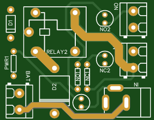 🔋 DIY Solar-Based Mini IPS at Home | Auto Load Changeover Circuit for 12V DC Fan/Light
If you're looking for an easy and affordable solution to keep your 12V DC fan or light running even ...
-
 🔋 DIY Automatic Cut Off 12V Trickle Charger | Lead Acid Battery AutoCut Charger
Do you often charge your 12V lead-acid battery manually and worry about overcharging? With this DIY ...
-
 🔥 DIY Smart 12V Battery at Home | Using 18650 Cells + Smart BMS
Looking for a way to build a powerful and smart 12V battery at home? In this guide, I'll show you h...
-
 🎮 DIY Arduino Nano Snake Game Console with OLED Display
DIY Arduino Nano Snake Game Console with OLED Display and ButtonsDo you love retro games? Want to bu...
-
 DIY 150W IPS Making At Home with Auto Changeover System | Mini IPS 2025
How to Make an Automatic 150W IPS Using Two Circuit ModulesAre you looking for a reliable and effici...
-
-
mammoth-3D SLM Voron Toolhead – Manual Drill & Tap Edition
69 0 0 -
-
AEL-2011 Power Supply Module
587 0 2 -
AEL-2011 50W Power Amplifier
531 0 2 -
-
-
Custom Mechanical Keyboard
729 0 0 -
Tester for Touch Screen Digitizer without using microcontroller
361 2 2 -
Audio reactive glow LED wristband/bracelet with NFC / RFID-Tags
333 0 1 -
-


