Hello readers! I hope you are doing well. Welcome to the detailed guide on the introduction to the current divider. Electrical circuits are all about the right current flow from one point to the other; therefore, the right current analysis is a crucial step before working on any circuit. The current divider is a fundamental concept in studying the electronic flow in parallel circuits, and the most important point is that the current flowing through any component depends on the electrical resistance value. It helps in the right current distribution and by careful study of the circuit’s values, the engineers, designers, and manufacturers can carefully design and create the circuits, effectively troubleshoot the electrical system, and ensure the circuit's health through an appropriate amount of current.

In this article, I am going to share the basic introduction of the current divider, its properties, and its basic concepts. Then we’ll have a look at the derivation of different equations using Kirchoff’s current rule and Ohm’s law. After that, we’ll see some basic examples to understand the core concept and in the end, the discussion will be about its applications. Let’s get started.
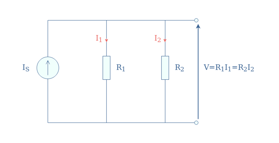
The current divider is the parallel circuit, defined as the electrical configuration in which the electrical current is divided into different paths or branches and the voltage level across each component is the same. The resistive elements are connected parallel to each other, and the whole current is divided into different paths according to the resistance value of the path. Basically, the circuit consists of different types of components, such as inductors, resistors, capacitors, and many others, and each component has its own resistance value.
While studying the parallel circuits, two concepts are crucial to keep in mind:
VR1 = VR2 = VR3….VRn
Therefore, knowing the voltage value of a single resistor’s source is enough to calculate the overall voltage difference across the circuit.
Let’s understand the current divider circuit with the help of the most straightforward circuit. The two fundamental concepts of electrical current analysis that are utilized to understand the current flow in the circuit are:
The current is divided into two paths, P1 and P2, containing the resistors R1 and R2. The potential difference applied through any source, such as a battery, is indicated by V, and the current passing through nth resistor is indicated by IRn. Hence, the current passing through R1 is IR1 and for R2, it is indicated by IR2. The following is the image of a circuit:

The IT indicated the total current, and as you can see, the flow of this current starts from the positive terminal of the battery and is divided into different paths. On the other end of this circuit, the current passing through each path sums up, and the total current then reaches the negative terminal of the battery. This is what Kirchoff’s current law (KCL) says:
The sum of all the currents passing through the node or a junction is always equal to zero
In other words:
The current of not entering the node must always equal the current leaving the node.
Mathematically,
∑Iin=∑Iout
Here,
∑Iin= total current entering the junction
∑Iout-= total current leaving the junction
Rearranging the above equation gives us a more simplified and relative statement for the same rule that is:
The total current passing through the parallel circuit is the sum of all the currents passing through each path.
Mathematically, we express this as:
IT = IR1 + IR2 …….. Eq 1
This helps us a lot, not only with the calculation of the total current but also to know the current flowing in a single path or resistor. For this, just use the simple rule of equation:
IR1 = IT – IR2 …….. Eq 2
Similarly, for current from R2,
IR2 = IT – IR1 …….. Eq 3
Now let’s consider Ohm’s law to find the individual code current in the circuit if unknown. This law states:
The voltage of the conductor is directly proportional to the current flowing through it and the resistance of the conductor.
This is shown mathematically as follows:
V=IR …….. Eq 4
In our case, the eq 4 becomes:
V=InRn …….. Eq 5
Hence for R1
V=I1R1 …….. Eq 6
And for R2
V=I2R2 …….. Eq 7
Rearranging the equations 6 and 7 makes the following:
I1=V/R1 …….. Eq 8
I2=V/R2 …….. Eq 9
Incorporate values of equations 8 and 9 in equation 1:
IT=V/R1+V/R2
IT=V(1/R1+1/R2)
V=IT(1/R1+1/R2)-1
V=IT(R2 R1/R1+R2) ….. Eq 10
Now, we can find the individual current through equation 9 as well, and for this, put equation 10 in eq 8
I1=[IT(R2 R1/R1+R2)]/R1
I1=[IT(R2 R1/R1+R2)]/R1
I1=IT((1/R1)+(1/R2)1/R,)
I1=IT(R2/R1+R2) ….. Eq 11
Similarly, for I2,
I2=IT((R1/R2+R1) ….. Eq 12
These two equations are crucial in the analysis of different parallel circuits, and we’ll utilize them in our coming examples to prove their integrity. The concept can be enhanced to the n resistors if the circuit contains n number of resistors.
Another point to mention here is the measurement of the equivalent resistance. Just like the current, the equivalent resistance in the parallel circuit is the one that would cause the same effect as the sum of all the resistors in the circuit. It is represented as the reciprocal of each resistance, and mathematically, it is shown as:
1/Req=1/R1+1/R2……1/Rn
Here,
Req= Equivalent resistance
R1= Resistance of resistor 1
R2= Resistance of resistor 2
Rn= Resistance of resistor n
Keep in mind that the current in an individual path is obtained by using the resistance of the opposite path on the numerator. Many students find it difficult to remember the formulas and mix them up.
Let us implement the equation in circuits to find different parameters of the circuit. This is a good practice for understanding the current divider circuits and the equation we have just derived. All of these are for the parallel circuits, and I am going to share the simplest example first and will move towards the more complicated ones gradually.
A circuit containing the voltage 12V has two paths, P1 and P2. Each of these has resistors, and the value of R1 is 20 ohm and R2 is 30 ohm. Find the total current flowing through the circuit and the individual currents of each path.

Here,
V=12V
R1=20 Ohm
R2= 30 Ohm
IR1=?
IR2=?
IT=?
Using the equation 6 for R1:
I1=V/R1
I1=12/20
I1=0.6A
Using the equation 7 for R2:
I2=V/R2
I2=12/30
I2=0.4A
Now, it is time to find the total current flowing through the circuit using Equation 1
IT = IR1 + IR2
IT = 0.6+0.4
IT = 1A
A resistor has three resistances with the values 10 Ohm, 20 Ohm, and 30 Ohm respectively. The total current flowing through the circuit is 5A. Calculate the current flowing through each path.

Examining the problem statement gives us the following data:
R1=10 Ohm
R2=20 Ohm
R3=30 Ohm
IT=5A
I1=?
I2=?
I3=?
Let’s find all one by one.
1/Req=1/R1+1/R2+1/R3
1/Req=1/10+1/20+1/30
1/Req=0.1+0.05+0.0333
1/Req=0.1833 ohm
Req=1/0.18333
Req=5.45 ohms
To find the singular current flowing through I1, here is the formula:
I1 = IT * (R2 * R3) / ((R1 * R2) + (R2 * R3) + (R1 * R3))
I1=5 * (20 * 30) / (1200)
I1=2.73 A
Similarly,
I2 = IT* (R1 * R3) / ((R1 * R2) + (R2 * R3) + (R1 * R3))
I2=5 * (10 * 30) / (1200)
I2=1.36 A
For the calculation of I3
I3 = IT * (R1* R2) / ((R1 * R2) + (R2 * R3) + (R1 * R3))
I3 = 5 * 5 * (10 * 20) / (1200)
I3 = 0.91 A
Now, let’s verify the result. Using our equation 1, the equivalent current must be equal to the total current given in the problem statement.
IT=I1+I2+I3
5=2.73+1.36+0.91
5=5
Hence the equation is satisfied, and we proved the current divider rule.
The current divider rule is not only utilized for pure parallel circuits but also for calculating the part of a numerical circuit containing a parallel connection. Here is an example of a combination of parallel and series connections.
A circuit is connected to a 30 V battery source and contains three resistances having 10-ohm values in each of them. Find the total current of the circuit along with the current passing to the third resistor.

Here,
V=30 V
R1=10 ohm
R2=10 ohm
R3=10 ohm
IT=?
I3=?
Using the current divider rule,
Req=R1+(R2* R3/R2+R3) because only R2 and R3 are connected parallel to each other.
Req=10+(10* 10/10+10)
Req=10+(100/20)
Req=10+5
Req=15 Ohm
Now for IT
IT=V/Req
IT=30/15
IT=2A
To solve the last part of this problem through the current divider rule, let’s consider the unknown value of the resistor as K.
K=R2 * (R3/R2+R3)
K=10 *(10/10+10)
K=10 * (10/20)
K=10 * 0.5
K=5 Ohm
Now,
I2=IT * (5/R3)
I2=2* (5/10)
I2=2* 0.5
I2=1A
The following are some common examples of current divider applications:

The transistors work best in a certain range of current, and the current divider circuit can be applied to an emitter, base, or resistor within that specific range. This not only helps in the right output generation but the desired operating range results in optimal performance. For instance, the current divider circuit helps in setting the quiescent current when designed with the common emitter circuit.
As done in the example above, the main purpose of the current divider circuit is to find the current in the individual path to ensure every component is getting enough current. This is crucial to have optimal performance with the perfect component health.
The analog circuits show continuous values and the current divider helps in the precise current control. This circuit divides the current into smaller ones and the analog circuit then represents the small current values at each step more precisely and, as a result, provides the optimal performance.
Moreover, the issues of the analog circuit, such as fluctuation in the values or attenuation, are easily dealt with in the current divider circuit. It is done by careful control of the individual resistor values and this helps in the analog process such as signal amplification, attenuation, and current distribution.
In the LED control circuits, the brightness of the LEDs is controlled through the amount of current passing through it. The current dividers are crucial to provide the appropriate amount of current to the LED because more amount can cause the LED damage.
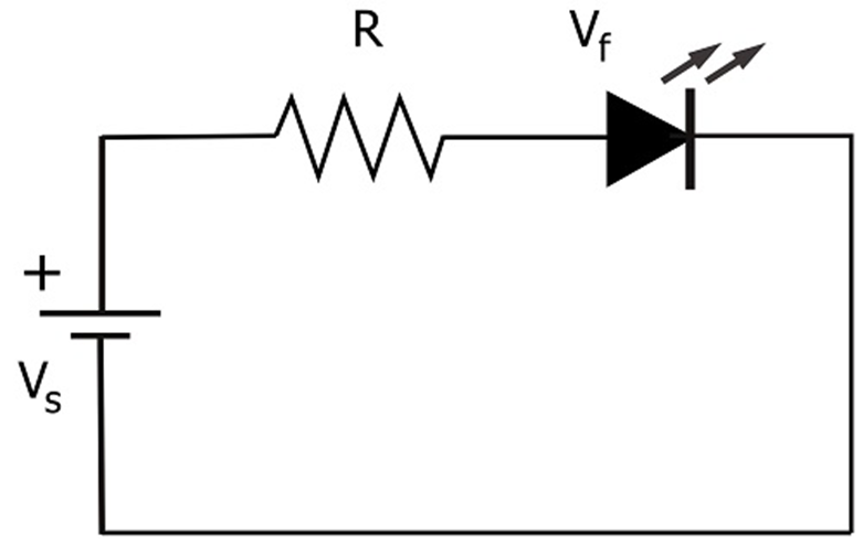
Similarly, the less amount of current can also cause the damage or dulness in the LED and when a circuit contains more than one LED, the current divider helps in finding the amount of current passing through individual LED.
Hence today, we have seen a lot about the current divider circuit and learnt its basic introduction. I hope you got your desired information.
 Log in to post comments.


