Hi all,
For a project I created a custom PCB.
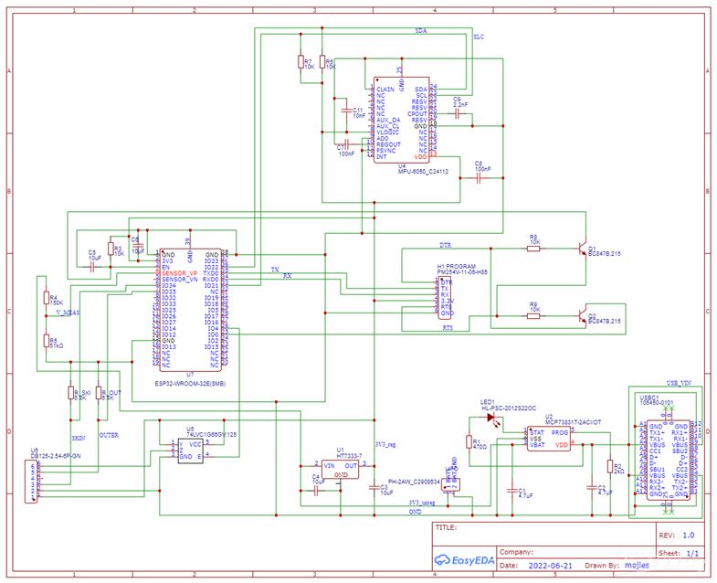
It's a LiPo powered PCB with ESP32-WROOM-32E module, Lipo charging module, 3.3V Voltage regulator and MPU6050 Acc/Gyro unit. Charging via USB-C connector. The ESP-32 module being programmed by using a programming header (and external FTDI232 module, to be attached on position “H1:program” in the schematic below.)
After uploading the code and powering via the FTDI232 module, attached to my USB port in computer (LiPo and USB-C disconnected) everything runs fine.
But when trying to power only from LiPo (2000mah) and even when supported with charging power from USB the script________ is triggering a Brownout Detector error. When uploading a blink________ or ‘bare minimum’ script________ everything is working fine om LiPo-only power. My assumption is that the final script________ (using Wifi, BLE, MPU sensor) is triggering the error while consuming to much current? But I don’t understand why I don’t have this issue when powering via FTDI232 module.
Is my schematic correct (looking at the choice of voltage regulator HT7333-7, placing of capacitors etc)? Any suggestions how I could further investigate and solve the error in a future design are really welcome.
Thanks,
Mojies