|
|
NI MultisimNI
|
|

|
AltiumAltium
|
Adjustable Power Supply Based on LM317T
Adjustable Power Supply Based on LM317T
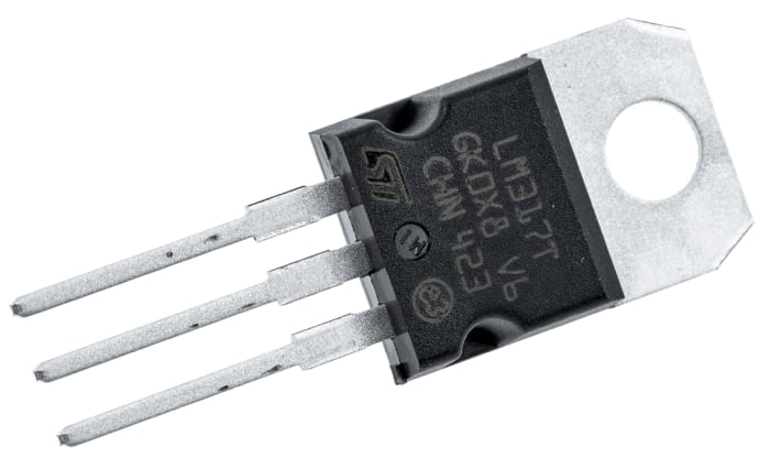
LM317 3-Terminal Adjustable Regulator

The LM317 device is an adjustable three-terminal positive-voltage regulator capable of supplying more than 1.5 A over an output-voltage range of 1.25 V to 37 V. It requires only two external resistors to set the output voltage. The device features a typical line regulation of 0.01% and typical load regulation of 0.1%. It includes current limiting, thermal overload protection, and safe operating area protection. Overload protection remains functional even if the ADJUST terminal is disconnected.
Features
- Output voltage range adjustable from 1.25 V to 37 V
- Output current greater than 1.5 A
- Internal short-circuit current limiting
- Thermal overload protection
- Output safe-area compensation
Datasheet: https://bit.ly/3jGasNo
After drawing the circuit diagram, I designed and simulated it on Multisim. According to the simulation result, I made the schematic drawing in Altium Designer and edited it by transferring it to the PCB.
What is MultiSIM ?

...
NI Multisim (formerly MultiSIM) is an electronic schematic capture and simulation program which is part of a suite of circuit design programs, along with NI Ultiboard.
Multisim is one of the few circuit design programs to employ the original Berkeley SPICE based software simulation. Multisim was originally created by a company named Electronics Workbench Group, which is now a division of National Instruments. Multisim includes microcontroller simulation (formerly known as MultiMCU), as well as integrated import and export features to the printed circuit board layout software in the suite, NI Ultiboard.
Multisim is widely used in academia and industry for circuits education, electronic schematic design and SPICE simulation.
...
Establishing the Circuit in Multisim and Displaying the Required Voltage Values and Waveforms with an Oscilloscope

Circuit Diagram Drawn in Altium Designer

Components

Mirrored and Straight Views of Printed Circuitry Drawn in Altium
Straight View

Mirrored View

Final Form of the Scheme to be Engraved on the Plate for the Printed Circuit Board
Straight View

Mirrored View

Since there was no access to the laser printer, the drawing of the schematic was made with an acetate pen on the copper plate and the excess coppers were melted in the prepared HCl & H2O2 solution and the remaining circuit paths were removed, then covered with solder and the components were soldered and the circuit was completed.
Drilling Holes to Place Components

Getting Started to Place and Solder Components

Components Placed and Soldered


I would be very grateful if you do not forget to vote and like.
Thank you for reading my article and reviewing my project.
Stay in touch with electronics.
e-mail : agoktugaydin.ece@gmail.com
medium blog : https://agoktugaydin.medium.com/
youtube : https://www.youtube.com/channel/UCGHJt1cBOxA5xkZSUaCg2vA


Adjustable Power Supply Based on LM317T
*PCBWay community is a sharing platform. We are not responsible for any design issues and parameter issues (board thickness, surface finish, etc.) you choose.
- Comments(0)
- Likes(5)
-
 Engineer
Jul 26,2024
-
 Engineer
Jul 19,2024
-
 rosario di palma
Mar 25,2024
-
 tripleclown
Dec 24,2022
-
 Engineer
Dec 14,2021
- 0 USER VOTES
- YOUR VOTE 0.00 0.00
- 1
- 2
- 3
- 4
- 5
- 6
- 7
- 8
- 9
- 10
- 1
- 2
- 3
- 4
- 5
- 6
- 7
- 8
- 9
- 10
- 1
- 2
- 3
- 4
- 5
- 6
- 7
- 8
- 9
- 10
- 1
- 2
- 3
- 4
- 5
- 6
- 7
- 8
- 9
- 10
 More by agoktugaydin
-
-
mammoth-3D SLM Voron Toolhead – Manual Drill & Tap Edition
140 0 0 -
-
AEL-2011 Power Supply Module
654 0 2 -
AEL-2011 50W Power Amplifier
567 0 2 -
-
-
Custom Mechanical Keyboard
769 0 0 -
Tester for Touch Screen Digitizer without using microcontroller
395 2 2 -
Audio reactive glow LED wristband/bracelet with NFC / RFID-Tags
364 0 1 -
-


