Arduino Based Weather Station
Introduction
An Arduino-based weather station using a DHT11 sensor and a 16×2 LCD is a compact and accessible project for measuring and displaying real-time temperature and humidity data. The DHT11 sensor collects environmental information, while the LCD display visually presents it in a user-friendly format. This project serves as a hands-on introduction to Arduino programming and sensor integration, making it an ideal choice for beginners interested in DIY electronics and weather monitoring.
NOTE FOR FULL PROJECT :
https://electronicsworkshops.com/2023/09/12/arduino-based-weather-station/
Connections
DHT11 to Arduino:
Connect the DHT11 sensor’s VCC to Arduino’s 5V.
Connect the DHT11 sensor’s GND to Arduino’s GND.
Connect the DHT11 sensor’s DATA pin to any digital pin on Arduino (e.g., D2).
LCD to Arduino:
Connect the LCD’s VCC to Arduino’s 5V.
Connect the LCD’s GND to Arduino’s GND.
Connect the Arduino D3 Pin to LCD’S DB6 Pin
Connect the Arduino D4 Pin to LCD’S DB5 Pin
Connect the Arduino D5 Pin to LCD’S DB4 Pin
Connect the Arduino D6 Pin to LCD’S DB7 Pin
Connect the Arduino D11 Pin to LCD’S E Pin
Connect the Arduino D12 Pin to LCD’S RS Pin
Connect the Arduino Contrast pin (usually labeled VO) to the wiper of the potentiometer.
Connect one end of the potentiometer to 5V and the other end to GND.
Working Principle
The working principle of an Arduino-based weather station using a DHT11 sensor and a 16×2 LCD involves several steps:
Sensor Data Collection: The DHT11 sensor is responsible for collecting environmental data, specifically temperature and humidity. It operates by using a thermistor to measure temperature and a humidity-sensitive capacitor to measure humidity. The sensor converts these analog measurements into digital data that can be read by the Arduino.
Arduino Control: The Arduino serves as the brain of the weather station. It reads data from the DHT11 sensor through a digital pin and processes this data in its program (sketch).
Data Processing: Inside the Arduino sketch, the collected temperature and humidity data are processed. You can apply any necessary calibration or formatting to the raw sensor readings.
LCD Display: The processed data is then sent to the 16×2 LCD display. The LiquidCrystal library is typically used to control the display. The Arduino sends text and numerical values to the LCD, positioning them on the two rows of the screen. For example, it may display “Temperature: 25.5°C” on the first row and “Humidity: 50%” on the second row.
Updating Display: To keep the information up to date, the Arduino continuously reads data from the DHT11 sensor at predefined intervals (e.g., every few seconds or minutes) and updates the content on the LCD accordingly.
User Interaction: The LCD provides a visual interface for users to monitor the real-time temperature and humidity values without needing to access the Arduino’s code or a computer interface.
Power Supply: The Arduino and its components are powered through a suitable power source, such as a USB connection, a battery pack, or an external power supply, to ensure continuous operation.
Arduino Based Weather Station
*PCBWay community is a sharing platform. We are not responsible for any design issues and parameter issues (board thickness, surface finish, etc.) you choose.
- Comments(0)
- Likes(0)
- 0 USER VOTES
- YOUR VOTE 0.00 0.00
- 1
- 2
- 3
- 4
- 5
- 6
- 7
- 8
- 9
- 10
- 1
- 2
- 3
- 4
- 5
- 6
- 7
- 8
- 9
- 10
- 1
- 2
- 3
- 4
- 5
- 6
- 7
- 8
- 9
- 10
- 1
- 2
- 3
- 4
- 5
- 6
- 7
- 8
- 9
- 10
 More by Rabin Poudel
-
 Flood Detection and warning system using LORA and Arduino
IntroductionFloods are one of the most devastating natural disasters, causing immense damage to life...
-
 DIY LED Decoration Tiny Star PCB Project
IntroductionThe Tiny Star PCB is a small and fun DIY electronics project that is perfect for hobbyis...
-
 Simple and Cheap Clap Switch Circuit
IntroductionThe Simple and Cheap Clap Switch Circuit is a practical and fun DIY electronics project ...
-
 Arduino-based Mist Maker and Hand Dryer
IntroductionIn today’s world, automation and hygiene have become essential, especially in public pla...
-
 MPL3115A2 Barometric Pressure, Altitude, and Temperature Sensor
IntroductionThe MPL3115A2 is a highly accurate, low-power digital barometric pressure sensor from NX...
-
 E-Speaker Using ESP32
IntroductionThe E-Speaker is a smart, portable, and versatile audio system built using the ESP32 mic...
-
 Heart Rate Monitor Circuit Using Photoplethysmography (PPG)
IntroductionHeart rate is a vital physiological parameter that reflects the health and fitness of an...
-
 Automated Greenhouse Control System using ESP32
IntroductionAn automated greenhouse control system leverages technology to optimize plant growth con...
-
 STD CH330N USB to Serial Converter 5V
IntroductionThe CH330N is a versatile USB-to-serial converter chip that simplifies interfacing betwe...
-
 KY-032 Obstacle avoidance sensor module
IntroductionIntroduction to Obstacle Avoidance SensorsObstacle avoidance sensors are essential compo...
-
 BC547 BASED WATER LEVEL INDICATOR
IntroductionA water level indicator using a BC547 transistor is a simple and effective electronic pr...
-
 How to Design Own Arduino Wifi shield PCB
OverviewArduino wifi shield connects the Arduino with a wifi chip through the serial communication p...
-
 DIY Air Quality Tester
OverviewIn this project “DIY Air Quality Tester” we use Node MCU microcontroller and air quality sen...
-
 Digital Clock Using Arduino
OverviewIn this project, “Digital clock using Arduino” we will make a PCB board for digital clock an...
-
 Bluetooth Controlled car using Arduino
OverviewA Bluetooth Controlled Car Using Arduino is a fascinating DIY project that involves building...
-
 IoT-Based Automatic Street Light Controller Using ESP32
IntroductionThis system uses ESP32 modules to control street lights through a centralized IoT server...
-
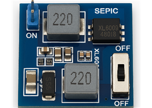 SEPIC DC-DC Converter Using the MT3608 Boost IC
IntroductionModern electronic design must prioritize effective and adaptable power management, parti...
-
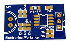 Audio Peak Detector using LMV358
IntroductionAn Audio Peak Detector is an essential circuit in audio signal processing that identifie...
-
-
AEL-2011 Power Supply Module
524 0 2 -
AEL-2011 50W Power Amplifier
485 0 2 -
-
-
Custom Mechanical Keyboard
693 0 0 -
Tester for Touch Screen Digitizer without using microcontroller
329 2 2 -
Audio reactive glow LED wristband/bracelet with NFC / RFID-Tags
310 0 1 -
-
-


