


|
|
Arduino Nano R3 |
x 1 | |
|
|
BD244 PNP transistor |
x 1 | |
|
|
Rotary Encoder with Push-Button |
x 1 | |
|
|
Buzzer |
x 1 | |
|
|
5V relay |
x 1 | |
|
|
LED |
x 3 | |
|
|
Resistor, 470 ohm |
x 3 | |
|
|
button |
x 1 |

|
Soldering iron (generic) |
|

|
Solder Wire, Lead Free |
|

|
arduino IDEArduino
|
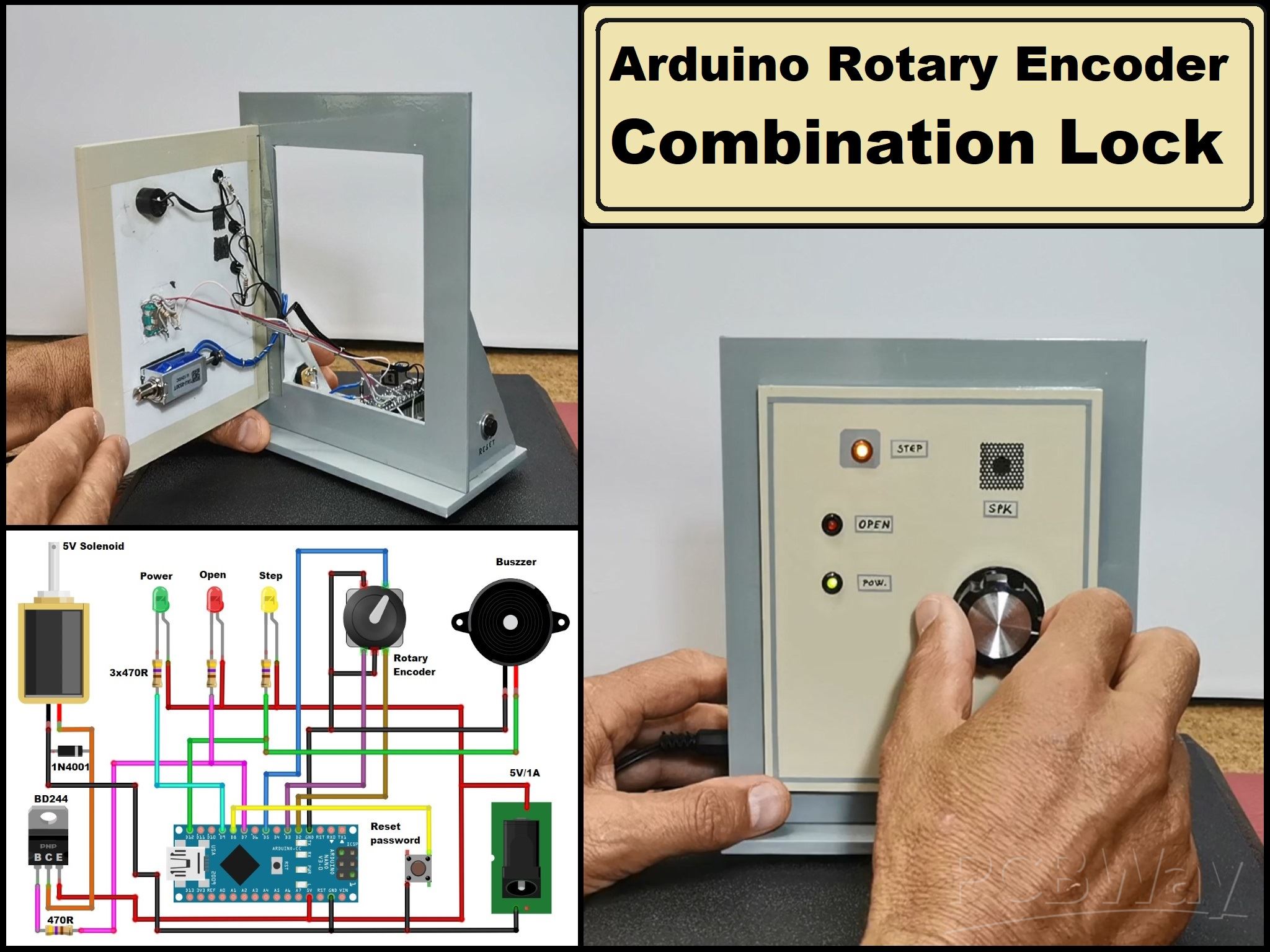
Arduino Rotary encoder combination lock (Arduino door lock system with Rotary Encoder)
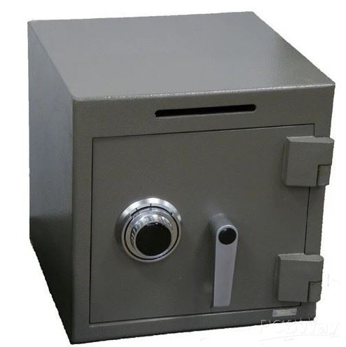
Rotary dial safes typically use a mechanical combination lock. They are valued for their simplicity, reliability, and resistance to tampering, making them a popular choice for securing valuables and sensitive items.
This time I will present you a very unusual and original way for a door lock system where the password is entered using a rotary encoder, in a way similar to above mentioned safes, with a certain combination of turning left and right. The source code was given in a post on the "arduino cc" forum without any more detailed explanations and a schematic diagram, so I decided to build the complete project and check the functionality.
I also made minor modifications and improved the functionality by adding a buzzer for the audio presentation of the number of encoder moves.
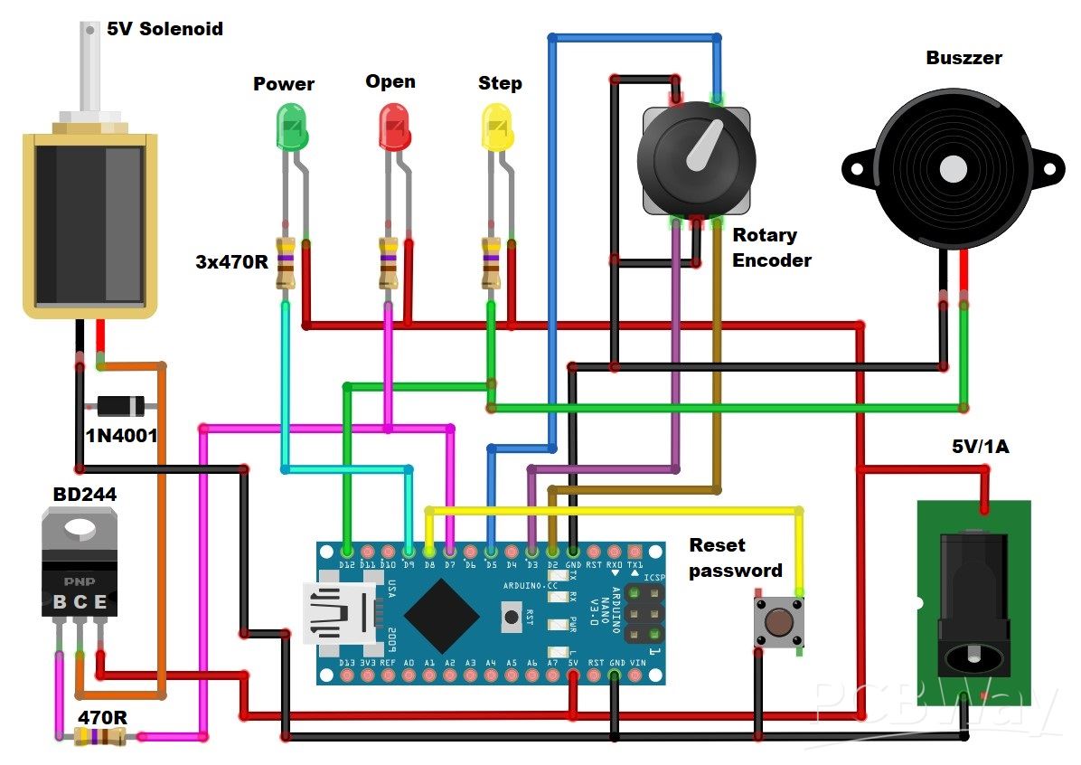
The device is relatively simple to make and consists of several components:
- Arduino Nano microcontroller board
- Rotary encoder with push button
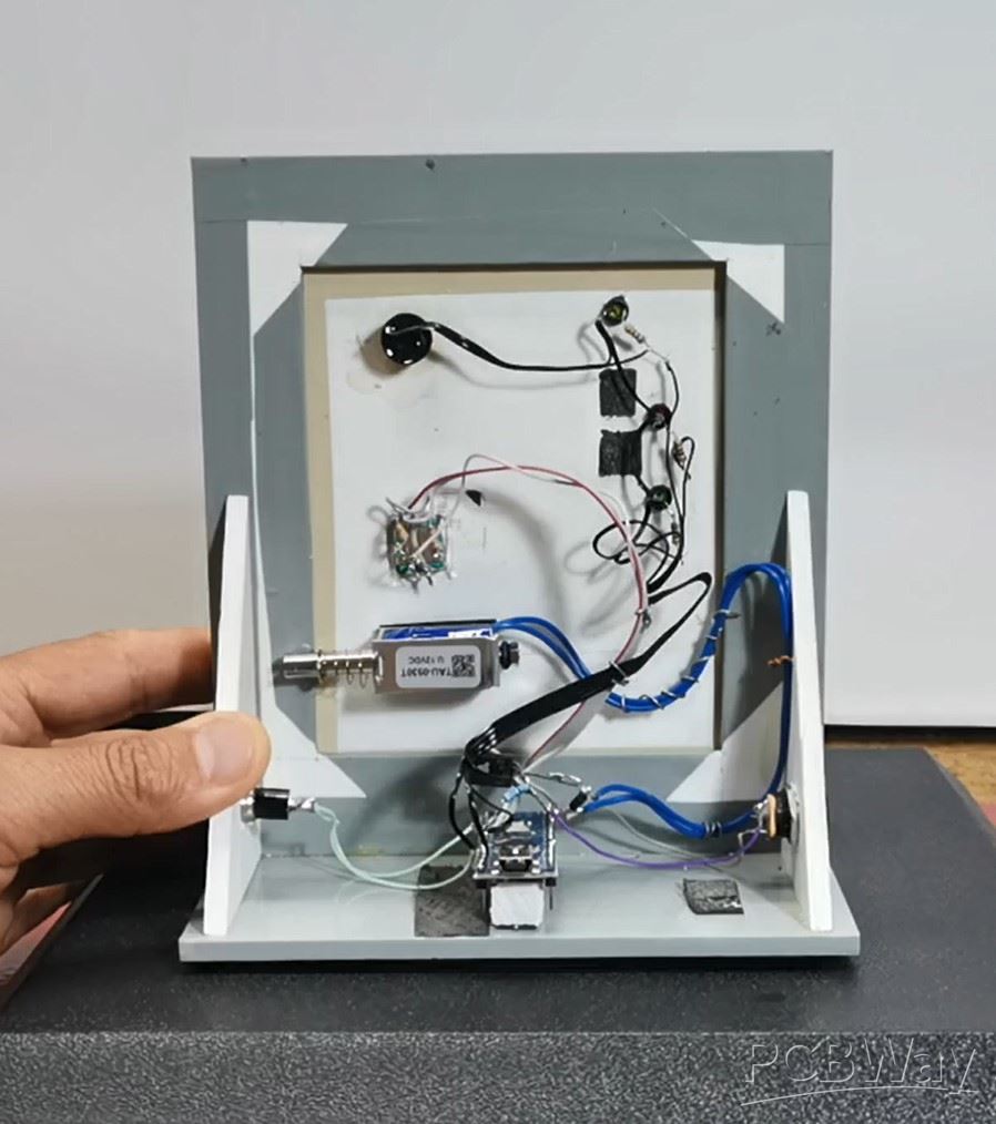
- 5V solenoid (you can notice that I am using a 12V solenoid, which works perfectly fine on 5V)
- BD238 or similar medium power PNP Transistor
- Button
- 3 Leds
- Active Buzzer
- and few Resistors
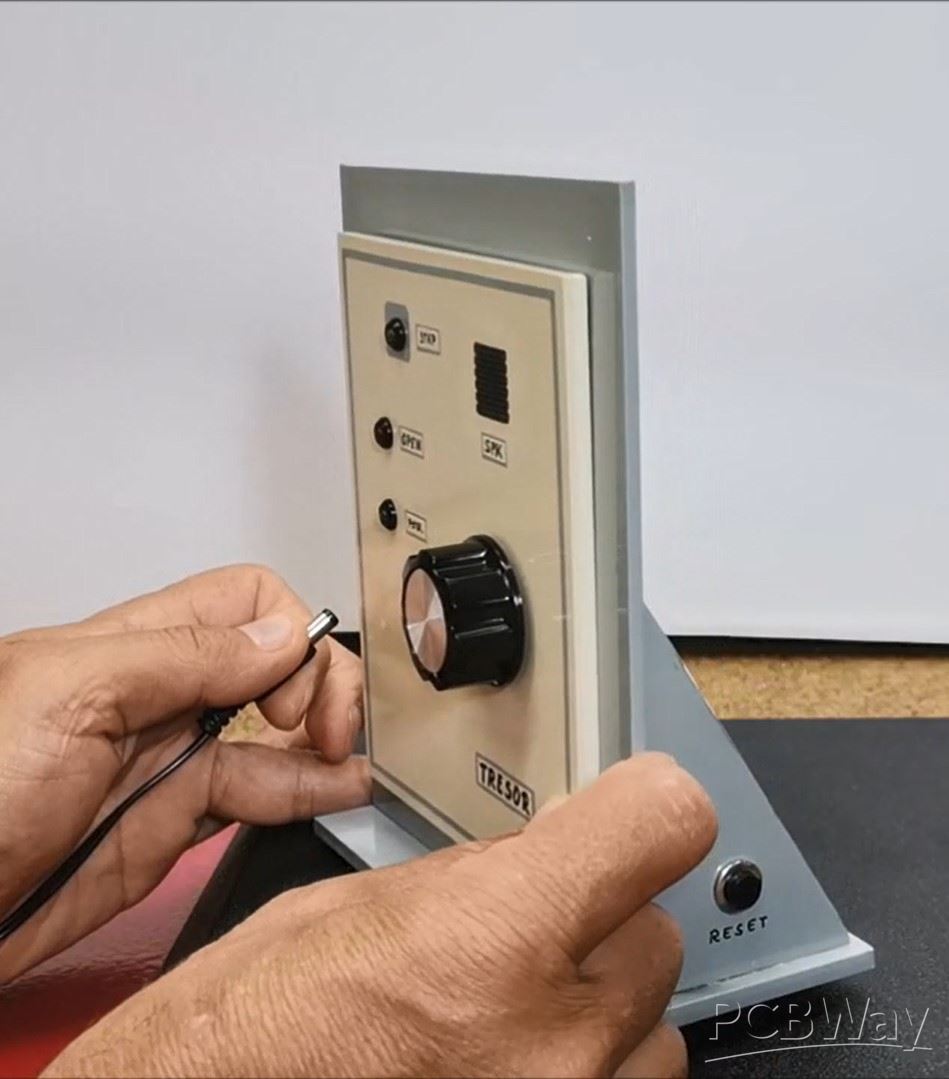
First, let me briefly explain the way of work. When turning on the device, the green power diode is activated, which indicates that the device is active. After 15 seconds of inactivity, the diode turns off, and the device is now in the standby position. By pressing the button of the rotary encoder, the lock is activated. The unlock code is entered by turning the rotary encoder to the left and right a certain number of steps.

The number of entered steps is attached visually to the yellow LED, and to the buzzer in the form of short beeps. When the correct password is entered, the button from the rotary encoder is pressed and the solenoid is activated, and at the same time the red LED lights up, which indicates that the door is open. After a certain time of several seconds which is defined in the code, the solenoid is deactivated again. The default password entered in the code is 221 (2 right - 2 left - 1 right - button) but we can change it as described later in the video. To reset the default password, we need to hold down the RESET button and turn on the device.
When setting a new password you can vary the number of tumblers as well as the range of valid numbers. As is, with five tumblers and forty possible numbers, there are over one hundred million possible combinations. Let me mention that the first number of the combination must be turned clockwise and each succeeding number alternates direction.
And now let's see how the device works in real conditions
When turning on the device, a green LED lights up and we can enter the password. First, I use the default password, which is 221 (2 right, 2 left, 1 right). After a few seconds, the solenoid returns to its original state.
Now to enter a new password, press the button while the red LED is on, and the yellow LED starts flashing. Next we enter the new password and press the button, and again to confirm. So the new password is set.
And finally a short conclusion. This is a very original, effective, and interesting example of a safe lock, which is almost identical to the large factory safes and thanks to the use of a microcontroller is very simple to make. For the sake of simplicity, the device is mounted in an open box that represents only the front panel of the safe.

Arduino Rotary encoder combination lock (Arduino door lock system with Rotary Encoder)


- Comments(0)
- Likes(1)
More by Mirko Pavleski
-
 Arduino 3D Printed self Balancing Cube
Self-balancing devices are electronic devices that use sensors and motors to keep themselves balanc...
Arduino 3D Printed self Balancing Cube
Self-balancing devices are electronic devices that use sensors and motors to keep themselves balanc...
-
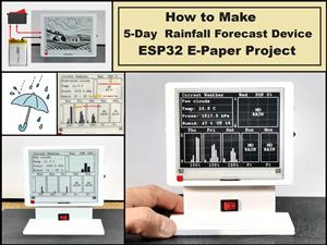 DIY 5-Day Rainfall Forecast Device - ESP32 E-Paper Project
In several of my previous projects I have presented ways to make weather stations, but this time I ...
DIY 5-Day Rainfall Forecast Device - ESP32 E-Paper Project
In several of my previous projects I have presented ways to make weather stations, but this time I ...
-
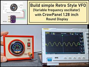 Build simple Retro Style VFO (Variable frequency oscillator) with Crowoanel 1.28 inch Round Display
Today I received a shipment with a Small round LCD display from Elecrow. The device is packed in tw...
Build simple Retro Style VFO (Variable frequency oscillator) with Crowoanel 1.28 inch Round Display
Today I received a shipment with a Small round LCD display from Elecrow. The device is packed in tw...
-
 Human vs Robot – Rock Paper Scissors with MyCobot 280 M5Stack
Today I received a package containing the few Elephant Robotics products. The shipment is well pack...
Human vs Robot – Rock Paper Scissors with MyCobot 280 M5Stack
Today I received a package containing the few Elephant Robotics products. The shipment is well pack...
-
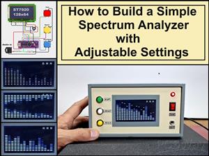 How to Build a Simple Audio Spectrum Analyzer with Adjustable Settings
An audio spectrum analyzer is an electronic device or software tool that measures and visually disp...
How to Build a Simple Audio Spectrum Analyzer with Adjustable Settings
An audio spectrum analyzer is an electronic device or software tool that measures and visually disp...
-
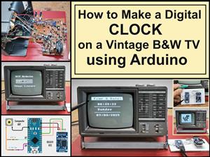 How to Make a Digital Clock on a Vintage B&W TV using Arduino
These days I accidentally came across this small retro Black and White TV with a built-in Radio, so ...
How to Make a Digital Clock on a Vintage B&W TV using Arduino
These days I accidentally came across this small retro Black and White TV with a built-in Radio, so ...
-
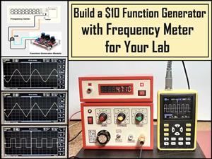 Build a $10 Function Generator with Frequency Meter for Your Lab
A function generator is a piece of electronic test equipment used to generate various types of elec...
Build a $10 Function Generator with Frequency Meter for Your Lab
A function generator is a piece of electronic test equipment used to generate various types of elec...
-
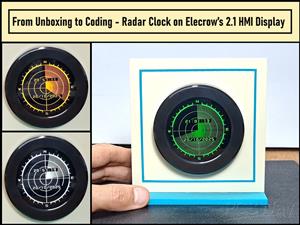 From Unboxing to Coding - Radar Clock on Elecrow’s 2.1 HMI Display
Today I received a shipment with a large round LCD display from Elecrow. The device is packed in two...
From Unboxing to Coding - Radar Clock on Elecrow’s 2.1 HMI Display
Today I received a shipment with a large round LCD display from Elecrow. The device is packed in two...
-
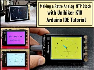 Making a Retro Analog NTP Clock with Unihiker K10 - Arduino IDE Tutorial
Some time ago I presented you a way to use standard Arduino libraries on the Unihiker k10 developme...
Making a Retro Analog NTP Clock with Unihiker K10 - Arduino IDE Tutorial
Some time ago I presented you a way to use standard Arduino libraries on the Unihiker k10 developme...
-
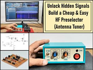 Build a Cheap & Easy HF Preselector - Antenna Tuner
HF antenna preselector is an electronic device connected between an HF radio antenna, and a radio r...
Build a Cheap & Easy HF Preselector - Antenna Tuner
HF antenna preselector is an electronic device connected between an HF radio antenna, and a radio r...
-
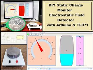 DIY Static Charge Monitor - Electrostatic Field Detector (Arduino & TL071)
A Static Charge Monitor also known as a Static Field Meter or Electrostatic Voltmeter is a device u...
DIY Static Charge Monitor - Electrostatic Field Detector (Arduino & TL071)
A Static Charge Monitor also known as a Static Field Meter or Electrostatic Voltmeter is a device u...
-
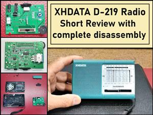 XHDATA D-219 Radio Short Review with complete disassembly
Some time ago I received an offer from XHDATA to be one of the first test users of their new radio m...
XHDATA D-219 Radio Short Review with complete disassembly
Some time ago I received an offer from XHDATA to be one of the first test users of their new radio m...
-
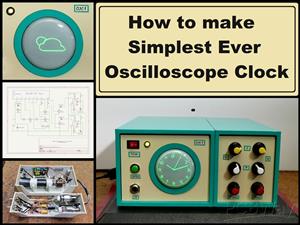 How to make Simplest ever Oscilloscope Clock
An oscilloscope clock is a unique and creative way to display the time using an oscilloscope, which...
How to make Simplest ever Oscilloscope Clock
An oscilloscope clock is a unique and creative way to display the time using an oscilloscope, which...
-
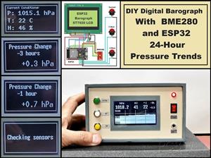 DIY Digital Barograph with BME280 and ESP32 - 24 Hour Pressure Trends
A barograph is a self-recording barometer that continuously measures and records atmospheric pressu...
DIY Digital Barograph with BME280 and ESP32 - 24 Hour Pressure Trends
A barograph is a self-recording barometer that continuously measures and records atmospheric pressu...
-
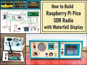 Build a Raspberry Pi Pico SDR Radio with Waterfall Display
Software-defined radio (SDR) is a radio communication system where components that have traditional...
Build a Raspberry Pi Pico SDR Radio with Waterfall Display
Software-defined radio (SDR) is a radio communication system where components that have traditional...
-
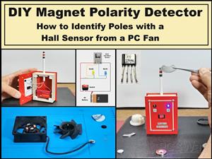 DIY Magnet Polarity Detector - How to Identify Poles with a Hall Sensor from a PC Fan
Recently, while working on a project, I needed to determine the polarity of several permanent magne...
DIY Magnet Polarity Detector - How to Identify Poles with a Hall Sensor from a PC Fan
Recently, while working on a project, I needed to determine the polarity of several permanent magne...
-
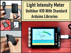 Light Meter Project - Making Dfrobot Unihiker K10 Work with Standard Arduino Libraries
The other day I received a shipment with a UNIHIKER K10 development board from DFRobot, which I rec...
Light Meter Project - Making Dfrobot Unihiker K10 Work with Standard Arduino Libraries
The other day I received a shipment with a UNIHIKER K10 development board from DFRobot, which I rec...
-
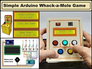 DIY Simple Arduino Whack-a-Mole Game
A "Whack-a-Mole" game is a classic arcade-style game where moles pop up randomly from holes, and th...
DIY Simple Arduino Whack-a-Mole Game
A "Whack-a-Mole" game is a classic arcade-style game where moles pop up randomly from holes, and th...
-
-
-
-
Tester for Touch Screen Digitizer without using microcontroller
321 2 2 -
Audio reactive glow LED wristband/bracelet with NFC / RFID-Tags
306 0 1 -
-
-


