


Edoardo kinmami
JAPAN • + Follow


Description
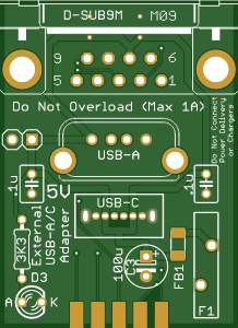
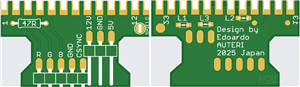
Commodore C64 C128 Power Supply Unit Saver e-Fuse
Tiny design. Fit the machines internally.
Tested with C64, C64C and C128.
Any kind of board revision.
Thermally resistant.
Based on TPS25200-Q1 5-V eFuse With Precision Adjustable Current Limit and Overvoltage Clamp.
Apr 13,2021
3,862 views
Commodore C64 C128 Power Supply Unit Saver e-Fuse
Provides excellent protection against OverCurrent, OverVoltage and ShortCircuit of 5V line. Internal solution.
3862
24
8
10.00 (1)
Published: Apr 13,2021
Standard PCB
BOM(Bill of materials)
Centroid file
PCBWay Donate 10% cost To Author
File Last Updated: 2023/08/18 (GMT+8)
File update record
2023-08-1807:14:57
Centroid file is updated.
Only PCB
PCB+Assembly
*PCBWay community is a sharing platform. We are not responsible for any design issues and parameter issues (board thickness, surface finish, etc.) you choose.


Under the
Attribution-ShareAlike (CC BY-SA)
License.


- Comments(8)
- Likes(24)
Upload photo
You can only upload 5 files in total. Each file cannot exceed 2MB. Supports JPG, JPEG, GIF, PNG, BMP
0 / 10000
VOTING
1 votes
- 1 USER VOTES
10.00
- YOUR VOTE 0.00 0.00

-
10design
-
10usability
-
10creativity
-
10content
10.00
More by Edoardo kinmami
-
 Commodore 64 1541-II 1581 Floppy Disk Drive C64 Power Supply Unit USB-C 5V 12V DIN connector 5.25
Compact design for high efficiency (>93%) USB-C Power Supply for Commodore 1541-II or 1581 Extern...
Commodore 64 1541-II 1581 Floppy Disk Drive C64 Power Supply Unit USB-C 5V 12V DIN connector 5.25
Compact design for high efficiency (>93%) USB-C Power Supply for Commodore 1541-II or 1581 Extern...
-
 V2 Commodore AMIGA USB-C Power Sink Delivery High Efficiency Supply Triple Output 5V ±12V OLED display ATARI compatible shark 100W
Version 2Compact design for high efficiency (>92%) USB-C Power Supply for Amiga 500, 600, 1200.Tw...
V2 Commodore AMIGA USB-C Power Sink Delivery High Efficiency Supply Triple Output 5V ±12V OLED display ATARI compatible shark 100W
Version 2Compact design for high efficiency (>92%) USB-C Power Supply for Amiga 500, 600, 1200.Tw...
-
 Commodore AMIGA PSU USB-C Power Sink Delivery Supply High Efficiency Triple Output 5V ±12V OLED ATARI ST shark
NEW VERSION https://www.pcbway.com/project/shareproject/V2_Commodore_AMIGA_USB_C_Power_Sink_Delivery...
Commodore AMIGA PSU USB-C Power Sink Delivery Supply High Efficiency Triple Output 5V ±12V OLED ATARI ST shark
NEW VERSION https://www.pcbway.com/project/shareproject/V2_Commodore_AMIGA_USB_C_Power_Sink_Delivery...
-
 Commodore AMIGA LED 500 600 1200 2000 status board multi system for debugging and troubleshooting hardware
A LED status PCB to connect A500, A600, A1200, A2000 motherboards for troubleshooting purposes witho...
Commodore AMIGA LED 500 600 1200 2000 status board multi system for debugging and troubleshooting hardware
A LED status PCB to connect A500, A600, A1200, A2000 motherboards for troubleshooting purposes witho...
-
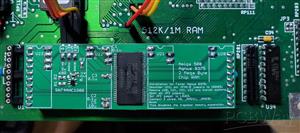
 Commodore MAX Machine RF modulator replacement S-VIDEO bypass
Inspired by projects from c0pperdragon, mbarszcz-pcb, tebl and VGP.It fits the commodore MAX MACHINE...
Commodore MAX Machine RF modulator replacement S-VIDEO bypass
Inspired by projects from c0pperdragon, mbarszcz-pcb, tebl and VGP.It fits the commodore MAX MACHINE...
-
 Enhanced Flash Floppy Drive Plus (internal) with push-buttons gotek
Enhanced Flash Floppy Drive Plus Improved Gotek for Commodore Amiga (internal and external), Atari, ...
Enhanced Flash Floppy Drive Plus (internal) with push-buttons gotek
Enhanced Flash Floppy Drive Plus Improved Gotek for Commodore Amiga (internal and external), Atari, ...
-
 Commodore Amiga DB23 RGB VGA External Video Buffer (V6) Compatible with GBS-8200 8220 OSSC No Jail bars
External RGB video adapter from DB-23 female (input) to DE-15F (output, VGA) for Amiga computers.Com...
Commodore Amiga DB23 RGB VGA External Video Buffer (V6) Compatible with GBS-8200 8220 OSSC No Jail bars
External RGB video adapter from DB-23 female (input) to DE-15F (output, VGA) for Amiga computers.Com...
-
 Commodore Amiga 500 Plus + Chip RAM expansion to 2MB for Fat Agnus 8375 Rev 8
Commodore Amiga 500 Chip RAM expansion to 2MB for Fat Agnus 8375 mounted onto Rev 8.No modification ...
Commodore Amiga 500 Plus + Chip RAM expansion to 2MB for Fat Agnus 8375 Rev 8
Commodore Amiga 500 Chip RAM expansion to 2MB for Fat Agnus 8375 mounted onto Rev 8.No modification ...
-
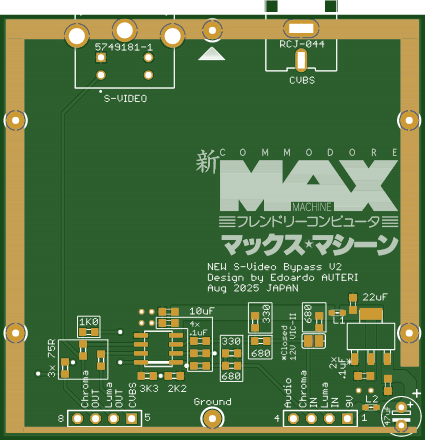 Commodore MAX Machine RF modulator replacement S-VIDEO COMPOSITE bypass V2
Inspired by projects from c0pperdragon, mbarszcz-pcb, tebl and VGP.It fits the commodore MAX MACHINE...
Commodore MAX Machine RF modulator replacement S-VIDEO COMPOSITE bypass V2
Inspired by projects from c0pperdragon, mbarszcz-pcb, tebl and VGP.It fits the commodore MAX MACHINE...
-
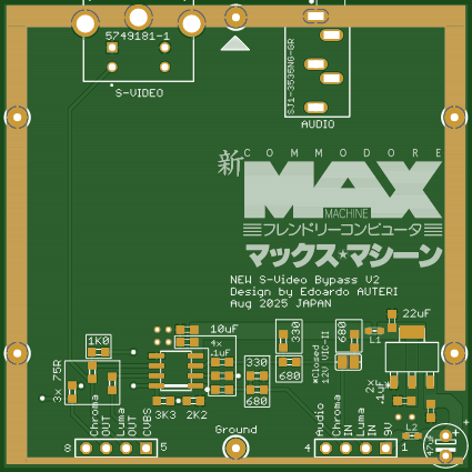 Commodore MAX Machine RF modulator replacement S-VIDEO AUDIO bypass V2
Inspired by projects from c0pperdragon, mbarszcz-pcb, tebl and VGP.It fits the commodore MAX MACHINE...
Commodore MAX Machine RF modulator replacement S-VIDEO AUDIO bypass V2
Inspired by projects from c0pperdragon, mbarszcz-pcb, tebl and VGP.It fits the commodore MAX MACHINE...
-
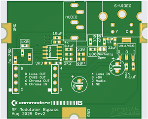 Commodore 16 (C16) Plus 4 RF modulator audio s-video replacement V2 C116 264 series
Commodore 16 (C16) & Plus/4 RF modulator replacementIt fits the commodore 16 & Plus/4 and re...
Commodore 16 (C16) Plus 4 RF modulator audio s-video replacement V2 C116 264 series
Commodore 16 (C16) & Plus/4 RF modulator replacementIt fits the commodore 16 & Plus/4 and re...
-
 Commodore Amiga Atari Joystick Pad Mouse External Passthrough USB 5V adapter with ESD protection 64 128 VIC-20
There is no longer a need for a 5V external power supply unit with a USB port.With this solution, Co...
Commodore Amiga Atari Joystick Pad Mouse External Passthrough USB 5V adapter with ESD protection 64 128 VIC-20
There is no longer a need for a 5V external power supply unit with a USB port.With this solution, Co...
-
 Commodore AMIGA Video connector breakout board DB 23 25 cable wiring SCART
BOM https://www.digikey.com/en/mylists/list/VZWCRA77CNThe board fits the plastic enclosure of a DB25...
Commodore AMIGA Video connector breakout board DB 23 25 cable wiring SCART
BOM https://www.digikey.com/en/mylists/list/VZWCRA77CNThe board fits the plastic enclosure of a DB25...
-
 Universal Breakout RGB EURO SCART PERITEL video game console OSSC computer
Fully compatible with Euro SCART cables. Provides all necessary components for connecting retro vide...
Universal Breakout RGB EURO SCART PERITEL video game console OSSC computer
Fully compatible with Euro SCART cables. Provides all necessary components for connecting retro vide...
-
 Universal Breakout RGB-J JP21 EIAJ TTC-003 XRGB MINI FRAMEMEISTER console computer
Minimal BOM and accurate signal conditioning enabling connections between any retro game console (or...
Universal Breakout RGB-J JP21 EIAJ TTC-003 XRGB MINI FRAMEMEISTER console computer
Minimal BOM and accurate signal conditioning enabling connections between any retro game console (or...
-
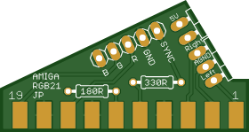 Commodore AMIGA 1000 500 600 2000 3000 4000 Breakout RGB-J JP21 EIAJ TTC-003 XRGB MINI FRAMEMEISTER
Minimal BOM and accurate signal conditioning enabling connections between Amiga models and XRGB Mini...
Commodore AMIGA 1000 500 600 2000 3000 4000 Breakout RGB-J JP21 EIAJ TTC-003 XRGB MINI FRAMEMEISTER
Minimal BOM and accurate signal conditioning enabling connections between Amiga models and XRGB Mini...
-
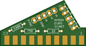 Commodore Amiga RGB SCART Breakout board 1000 500 600 1200 2000 3000 4000 EURO PERITEL OSSC
Fully compatible with Euro SCART cables. Provides all necessary components for connecting Amiga comp...
Commodore Amiga RGB SCART Breakout board 1000 500 600 1200 2000 3000 4000 EURO PERITEL OSSC
Fully compatible with Euro SCART cables. Provides all necessary components for connecting Amiga comp...
-
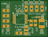 THS7374 4-Channel Rail-to-Rail Video Buffer for RGB, CVBS & CSYNC Signals
BOM list https://www.digikey.com/en/mylists/list/YLDCUPMRE3The THS7374 is a compact 4-channel rail-t...
THS7374 4-Channel Rail-to-Rail Video Buffer for RGB, CVBS & CSYNC Signals
BOM list https://www.digikey.com/en/mylists/list/YLDCUPMRE3The THS7374 is a compact 4-channel rail-t...
You may also like
-
-
mammoth-3D SLM Voron Toolhead – Manual Drill & Tap Edition
148 0 0 -
-
-
-
Tester for Touch Screen Digitizer without using microcontroller
402 2 2 -
Audio reactive glow LED wristband/bracelet with NFC / RFID-Tags
366 0 1 -
-


