


Enhanced Flash Floppy Drive Plus (internal) with push-buttons gotek
Enhanced Flash Floppy Drive Plus
Improved Gotek for Commodore Amiga (internal and external), Atari, Amstrad, Yamaha, etc.
FEATURES
· Complete support of DD/HD images with AT32F435RGT7 and STM32F105RBT (STM32 requires additional logics).
· Power-fail-safe and ESD/EMI-protected input, SD card (hot plug) and USB-A connectors.
· Connectors for OLED/LCD, STM32 blue pill board (OSD) and encoder/trackball.
· The internal version is fully compatible with 3D-printed enclosures and brackets, it fits any model.
· Optional MMC/SD slot.
· Prev/Next/Select-Eject-Insert long-shaft buttons or low-profile thumbwheel encoder with an integrated switch (thumbwheel layout is optional).
· The motor signal and second drive are available.
· Improved silkscreen, programming port, minimized BOM list.
· Hardware mistakes from the original "Gotek" fixed.
· Supports a loud magnetic or capacitive piezo.
· Optional 26-pin connector with solder jumpers to ensure broad compatibility with Amstrad, Yamaha, etc.
ACKNOWLEDGEMENT
· Flash Floppy is the firmware developed by Keir Fraser and available at https://github.com/keirf/flashfloppy .
· Keir Fraser has contributed to the design of the schematic.
DISCLAIMER
· Gerber and Centroid files, BOM list are subject to change without notice.
· The project is tested with the latest firmware (stable) version available at the time of writing.
https://www.digikey.com/en/mylists/list/A5GEAE8ACK

Enhanced Flash Floppy Drive Plus (internal) with push-buttons gotek
*PCBWay community is a sharing platform. We are not responsible for any design issues and parameter issues (board thickness, surface finish, etc.) you choose.


Raspberry Pi 5 7 Inch Touch Screen IPS 1024x600 HD LCD HDMI-compatible Display for RPI 4B 3B+ OPI 5 AIDA64 PC Secondary Screen(Without Speaker)
BUY NOW
ESP32-S3 4.3inch Capacitive Touch Display Development Board, 800×480, 5-point Touch, 32-bit LX7 Dual-core Processor
BUY NOW
Raspberry Pi 5 7 Inch Touch Screen IPS 1024x600 HD LCD HDMI-compatible Display for RPI 4B 3B+ OPI 5 AIDA64 PC Secondary Screen(Without Speaker)
BUY NOW


- Comments(20)
- Likes(25)
More by Edoardo kinmami
-
 Commodore AMIGA 1200 3000 4000 Dual Kickstart 27C800 EPROM DIL
It uses two 27C800 EPROMs (100~120ns). You need to select the upper and lower banks using a shunt.BO...
Commodore AMIGA 1200 3000 4000 Dual Kickstart 27C800 EPROM DIL
It uses two 27C800 EPROMs (100~120ns). You need to select the upper and lower banks using a shunt.BO...
-
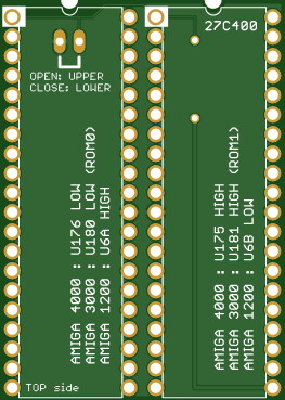 Commodore AMIGA 1200 3000 4000 Dual Kickstart 27C400 EPROM DIL
It uses two 27C400 EPROMs (100~120ns). You need to select the upper and lower banks using a shunt.BO...
Commodore AMIGA 1200 3000 4000 Dual Kickstart 27C400 EPROM DIL
It uses two 27C400 EPROMs (100~120ns). You need to select the upper and lower banks using a shunt.BO...
-
 COMMODORE AMIGA PC DOS STEREO AUDIO SAMPLER DIGITIZER PARALLEL PORT MASTER
Amiga Stereo Digitizer for Importing Audio Samples - Stereo Sound!This stereo digitizer/sampler was ...
COMMODORE AMIGA PC DOS STEREO AUDIO SAMPLER DIGITIZER PARALLEL PORT MASTER
Amiga Stereo Digitizer for Importing Audio Samples - Stereo Sound!This stereo digitizer/sampler was ...
-
 Commodore Amiga 500 Internal Dual Floppy Disk Drive Interface
In essence, this plug-in adapter for the Amiga 500 facilitates the simultaneous use of two types of ...
Commodore Amiga 500 Internal Dual Floppy Disk Drive Interface
In essence, this plug-in adapter for the Amiga 500 facilitates the simultaneous use of two types of ...
-
 74FCT646 74F646S 24 SOIC DIL AMIGA 3000 COMMODORE SOCKET ADAPTER SMT THT
An adapter to mount SMT 74FCT646 onto 24-DIL socket
74FCT646 74F646S 24 SOIC DIL AMIGA 3000 COMMODORE SOCKET ADAPTER SMT THT
An adapter to mount SMT 74FCT646 onto 24-DIL socket
-
 ATARI ST / STE RGB to VGA video Adapter with AV RCA JACK V2
Smart Solution for a Multisync Video Switch for Atari ST/STEAtari DIN13 to VGA3.5mm A/V jack connect...
ATARI ST / STE RGB to VGA video Adapter with AV RCA JACK V2
Smart Solution for a Multisync Video Switch for Atari ST/STEAtari DIN13 to VGA3.5mm A/V jack connect...
-
 Commodore 64 1541-II 1581 Floppy Disk Drive C64 Power Supply Unit USB-C 5V 12V DIN connector 5.25
Compact design for high efficiency (>93%) USB-C Power Supply for Commodore 1541-II or 1581 Extern...
Commodore 64 1541-II 1581 Floppy Disk Drive C64 Power Supply Unit USB-C 5V 12V DIN connector 5.25
Compact design for high efficiency (>93%) USB-C Power Supply for Commodore 1541-II or 1581 Extern...
-
 V2 Commodore AMIGA USB-C Power Sink Delivery High Efficiency Supply Triple Output 5V ±12V OLED display ATARI compatible shark 100W
Version 2Compact design for high efficiency (>92%) USB-C Power Supply for Amiga 500, 600, 1200.Tw...
V2 Commodore AMIGA USB-C Power Sink Delivery High Efficiency Supply Triple Output 5V ±12V OLED display ATARI compatible shark 100W
Version 2Compact design for high efficiency (>92%) USB-C Power Supply for Amiga 500, 600, 1200.Tw...
-
 Commodore AMIGA PSU USB-C Power Sink Delivery Supply High Efficiency Triple Output 5V ±12V OLED ATARI ST shark
NEW VERSION https://www.pcbway.com/project/shareproject/V2_Commodore_AMIGA_USB_C_Power_Sink_Delivery...
Commodore AMIGA PSU USB-C Power Sink Delivery Supply High Efficiency Triple Output 5V ±12V OLED ATARI ST shark
NEW VERSION https://www.pcbway.com/project/shareproject/V2_Commodore_AMIGA_USB_C_Power_Sink_Delivery...
-
 Commodore AMIGA LED 500 600 1200 2000 status board multi system for debugging and troubleshooting hardware
A LED status PCB to connect A500, A600, A1200, A2000 motherboards for troubleshooting purposes witho...
Commodore AMIGA LED 500 600 1200 2000 status board multi system for debugging and troubleshooting hardware
A LED status PCB to connect A500, A600, A1200, A2000 motherboards for troubleshooting purposes witho...
-
 Commodore MAX Machine RF modulator replacement S-VIDEO bypass
Inspired by projects from c0pperdragon, mbarszcz-pcb, tebl and VGP.It fits the commodore MAX MACHINE...
Commodore MAX Machine RF modulator replacement S-VIDEO bypass
Inspired by projects from c0pperdragon, mbarszcz-pcb, tebl and VGP.It fits the commodore MAX MACHINE...
-
 Enhanced Flash Floppy Drive Plus (internal) with push-buttons gotek
Enhanced Flash Floppy Drive Plus Improved Gotek for Commodore Amiga (internal and external), Atari, ...
Enhanced Flash Floppy Drive Plus (internal) with push-buttons gotek
Enhanced Flash Floppy Drive Plus Improved Gotek for Commodore Amiga (internal and external), Atari, ...
-
 Commodore Amiga DB23 RGB VGA External Video Buffer (V6) Compatible with GBS-8200 8220 OSSC No Jail bars
External RGB video adapter from DB-23 female (input) to DE-15F (output, VGA) for Amiga computers.Com...
Commodore Amiga DB23 RGB VGA External Video Buffer (V6) Compatible with GBS-8200 8220 OSSC No Jail bars
External RGB video adapter from DB-23 female (input) to DE-15F (output, VGA) for Amiga computers.Com...
-
 MP32C64 Commodore 64 VIC 20 Tape Datassette Audio MP3 AUDIOTAP TAP WAV PRG P00 T64 cartridge V2
The MP32C64 is a connection cartridge between a C64 or VIC-20 and another digital system such as MP3...
MP32C64 Commodore 64 VIC 20 Tape Datassette Audio MP3 AUDIOTAP TAP WAV PRG P00 T64 cartridge V2
The MP32C64 is a connection cartridge between a C64 or VIC-20 and another digital system such as MP3...
-
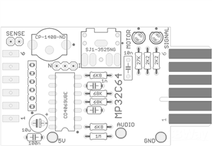 MP32C64 Commodore 64 VIC 20 Tape Datassette Audio MP3 AUDIOTAP TAP WAV PRG P00 T64 cartridge V1
The MP32C64 is a connection cartridge between a C64 or VIC-20 and another digital system such as MP3...
MP32C64 Commodore 64 VIC 20 Tape Datassette Audio MP3 AUDIOTAP TAP WAV PRG P00 T64 cartridge V1
The MP32C64 is a connection cartridge between a C64 or VIC-20 and another digital system such as MP3...
-
 Commodore AMIGA 500 600 2000 Kickstart 29F800 FLASH DIL TSOP
It uses a 29F800 FLASH (50~70ns). You need to select the upper and lower banks using a shunt.BOM lis...
Commodore AMIGA 500 600 2000 Kickstart 29F800 FLASH DIL TSOP
It uses a 29F800 FLASH (50~70ns). You need to select the upper and lower banks using a shunt.BOM lis...
-
 TL866 Adapter Commodore AMIGA 500 600 2000 1200 3000 4000 Kickstart 29F800 FLASH TSOP48
Adapter for the TL866 Universal Programmer.To use with https://www.pcbway.com/project/shareproject/C...
TL866 Adapter Commodore AMIGA 500 600 2000 1200 3000 4000 Kickstart 29F800 FLASH TSOP48
Adapter for the TL866 Universal Programmer.To use with https://www.pcbway.com/project/shareproject/C...
-
 Commodore AMIGA 1200 3000 4000 Dual Kickstart 29F800 FLASH DIL TSOP
It uses two 29F800 FLASH (50~70ns). You need to select the upper and lower banks using a shunt.BOM l...
Commodore AMIGA 1200 3000 4000 Dual Kickstart 29F800 FLASH DIL TSOP
It uses two 29F800 FLASH (50~70ns). You need to select the upper and lower banks using a shunt.BOM l...
-
Commodore AMIGA 1200 3000 4000 Dual Kickstart 27C800 EPROM DIL
It uses two 27C800 EPROMs (100~120ns). You need to select the upper and lower banks using a shunt.BO...
-
Commodore AMIGA 1200 3000 4000 Dual Kickstart 27C400 EPROM DIL
It uses two 27C400 EPROMs (100~120ns). You need to select the upper and lower banks using a shunt.BO...
-
COMMODORE AMIGA PC DOS STEREO AUDIO SAMPLER DIGITIZER PARALLEL PORT MASTER
Amiga Stereo Digitizer for Importing Audio Samples - Stereo Sound!This stereo digitizer/sampler was ...
-
Commodore Amiga 500 Internal Dual Floppy Disk Drive Interface
In essence, this plug-in adapter for the Amiga 500 facilitates the simultaneous use of two types of ...
-
74FCT646 74F646S 24 SOIC DIL AMIGA 3000 COMMODORE SOCKET ADAPTER SMT THT
An adapter to mount SMT 74FCT646 onto 24-DIL socket
-
ATARI ST / STE RGB to VGA video Adapter with AV RCA JACK V2
Smart Solution for a Multisync Video Switch for Atari ST/STEAtari DIN13 to VGA3.5mm A/V jack connect...
-
Commodore 64 1541-II 1581 Floppy Disk Drive C64 Power Supply Unit USB-C 5V 12V DIN connector 5.25
Compact design for high efficiency (>93%) USB-C Power Supply for Commodore 1541-II or 1581 Extern...
-
V2 Commodore AMIGA USB-C Power Sink Delivery High Efficiency Supply Triple Output 5V ±12V OLED display ATARI compatible shark 100W
Version 2Compact design for high efficiency (>92%) USB-C Power Supply for Amiga 500, 600, 1200.Tw...
-
Commodore AMIGA PSU USB-C Power Sink Delivery Supply High Efficiency Triple Output 5V ±12V OLED ATARI ST shark
NEW VERSION https://www.pcbway.com/project/shareproject/V2_Commodore_AMIGA_USB_C_Power_Sink_Delivery...
-
Commodore AMIGA LED 500 600 1200 2000 status board multi system for debugging and troubleshooting hardware
A LED status PCB to connect A500, A600, A1200, A2000 motherboards for troubleshooting purposes witho...
-
Commodore MAX Machine RF modulator replacement S-VIDEO bypass
Inspired by projects from c0pperdragon, mbarszcz-pcb, tebl and VGP.It fits the commodore MAX MACHINE...
-
Enhanced Flash Floppy Drive Plus (internal) with push-buttons gotek
Enhanced Flash Floppy Drive Plus Improved Gotek for Commodore Amiga (internal and external), Atari, ...
-
-
Commodore 64 1541-II 1581 Floppy Disk Drive C64 Power Supply Unit USB-C 5V 12V DIN connector 5.25
189 1 3 -
Easy to print simple stacking organizer with drawers
93 0 0 -
-
-
-
-
-
Modifying a Hotplate to a Reflow Solder Station
1163 1 6 -
MPL3115A2 Barometric Pressure, Altitude, and Temperature Sensor
653 0 1 -


what about the solder jumpers marked /CDI and SD CARD OFF ?
SD CARD OFF must be OPEN (floating) if you aim to use the SD CARD slot /CDI normally OPEN assuming that your slot does not invert the signal when the media is inserted, otherwise try /CDI closed with a solder blob
the revised power dissipation is not a concern. The p/n is correct.
Thanks for your quickly reply. We got it.
Okay, I have updated all optional part numbers (marked with an asterisk) to a quantity of 0
STM32F103C8T6 Blue pill is for OSD only not for managing the DD/HD. DD/HD images are managed by AT32F435RxT7 or STM32F105RBT. You can optionally have the STM32F103C8T6 mounted either with AT32F435RxT7 or STM32F105RBT.
I believe the schematic is detailed
you can solder only one CPU. The footprint is unique.
STM32F105RBT requires additional logics. AT32F435RxT7 does not. Optional logics are no need when a AT32F435RxT7 is selected.
the Assembly Instruction Drawing is now available for downloading.
· Complete support of DD/HD images with AT32F435RxT7 and STM32F105RBT (STM32 requires additional logics). · Power-fail-safe and ESD/EMI-protected input, SD card (hot plug) and USB-A connectors. · SD port instead of micro SD to facilitare insertion/extraction of media. · Connectors for OLED/LCD, STM32 blue pill board (OSD) and encoder/trackball. · Low-profile thumbwheel encoder with an integrated switch (option).