|
|
Solid state Tesla Coil |
x 1 | |
|
|
Lakhovsky antenna |
x 1 |

|
Soldering Iron Kit |
DIY Simple Functional Lakhovsky MWO (Multiwave Oscillator) Therapy Device
The Lakhovsky Multiwave Oscillator (LMO) is a device that was developed by Georges Lakhovsky in the early 20th century. Lakhovsky proposed this device as a form of alternative therapy, claiming it could restore the body's natural balance and promote healing through the use of electromagnetic frequencies. While his ideas and theories have been widely discredited and are not supported by mainstream science, some people continue to use his work as a basis for alternative medical treatments.

Some of benefits according to his claim are cell revitalization by increasing the oxygen supply and the nutritional value of the blood, and activation of the body's self-healing powers and increase of the general well-being.
Lakhovsky's machine worked on a different angle or principle to Rife's. It did not attack the microbes directly, but reinforced the vitality of the organism by accelerating cellular oscillation. It was intended to revitalise the oscillations of your normally healthy cells. It was therefor the reinforced organism that successfully resists the microbes and all pathogenic causes. The machine discharged high voltage that gives off electromagnetic pulses with an emphasis on producing the greatest number or widest range of frequencies/harmonics as possible, but it cannot maintain 1 steady frequency which was what Rife was doing to resonate a microbe to death.

This project is sponsored by PCBWay. This year, PCBWay organizes the Seventh Project Design Contest where, in addition to Electronic and Mechanical Project, also has been added a new category: STM32 Project. For the best selected projects are provided rich prizes in cash, coupons and special gifts. Submit your project for participation in this Contest from 2nd, Sep, 2024 to 19th, Jan, 2025. For more details and instructions visit the given page. Let PCBway always be your first choice.
The Multiple Wave Oscillator machine generally consists of two parts :
- high voltage and high frequency impulses source, usually a Tesla coil.
- and other part are two specially designed antennas.
First, let me explain the first part, which is the Tesla Transformer.

Its function is to generate an extremely high alternating voltage of the order of tens and up to hundreds of thousands of volts, under the action of which a variable magnetic field is created. In his original device, Lakhovski used a Spark Gap type of Tesla Transformer, and I use a Solid State type of Tesla Transformer, because it is much more durable, simpler to make, and more compact. I want to point out a few facts, because I had reactions after making the previous device like this, with claims that it was not originally made. Namely, every Tesla Transformer in the world has its own resonant frequency, regardless of whether it is a spark gap or Solid State. In fact, it is the shape of the antenna that generates a greater number of harmonics in a wide range of frequencies. Detailed instructions for making the Tesla Transformer that I will use in this project can be found in one of my previous videos.
In fact, Lakovski's discovery is the specially designed antennas (with Golden Ratio pattern) that act as toploads with several different capacities.

Each ring of his special antenna system radiated at a different wavelength and frequency dependent upon its diameter. The different size rings would set up interference patterns between themselves, producing a plethora of harmonic frequencies at many different wavelengths. The patient would be then exposed to a "MultiWave Oscillating Field".
Now let's test how this device behaves in real conditions:
To analyze the signals, the easiest way for me was to use my SDRPlay SD radio with the SDRUno companion software.

This small antenna serves to receive the emitted radiation. I will perform an analysis of the signal directly from the Tesla Transformer independently, as well as a comparison with the case when I connect Lakhovsky Antennas to it. I will repeat this test at several frequencies in the range of about 1 MHz, up to 300 MHz. The greatest potential difference is between the beginning and the end of the secondary winding of the Tesla transformer, so I will connect the antennas at those two points. The beginning of the winding is at a potential of practically 0 Volts, and at the end of the winding, in my case are induced about 50 thousand Volts. Since it is a modern SSTC powered at 30V through an isolation transformer, the risk of electric shock is very low (certainly eight during manufacture), unlike the original Spark Gap Tesla Coil used by Lakhowski, which is very expensive, it also spoils easily, and is dangerous for the patient. As I see, nowadays Spark gap Tesla coil is used by many self-builders of this type of device, probably not having enough knowledge and experience in the field of High Voltage.
The natural resonant frequency of this Tesla Coil is about 1.3 MHz, and around this frequency the two left and right harmonics can be observed. When measuring only with a connected tesla transformer, harmonics up to 50 MHz are registered. By connecting the Lakhovski antennas, this range has been extended to over 400 MHz, and it is significant to note that in this case (with connected antennas) the number of harmonics is drastically higher, and there is almost continuous radiation at all frequencies of the entire spectrum.

Perhaps this is not the most ideal experiment and I probably have some omissions, but with a high degree of certainty Lakhovski's claim that the shape of the antennas actually contributes to the generation of a large number of additional harmonics, so almost the entire spectrum is covered with oscillations, can be taken as correct. So we can take this claim as true, but only from a technical point of view.
And finally a short conclusion: In general, this invention of Lakhovsky is an ordinary tesla coil, which instead of a toroidal topload, has a so-called Lakhovsky antenna, which, by the way, according to my observations slightly amplifies the field in front of it and somewhat increases the emitted frequency and number of harmonics, thanks to the the way of making the antenna.
Of course, I am not a specialist in medicine and I will not comment in that domain at all. The idea of this experiment was to examine whether at least the technical side of this device is in the realm of truth.
SAFETY NOTE: Please do not attempt to recreate the experiments shown on this video unless you are familiar with High Voltage Safety Techniques! Direct Current even above 60V maybe lethal, even when the AC supply voltage has been disconnected due to the stored energy in the capacitors.


DIY Simple Functional Lakhovsky MWO (Multiwave Oscillator) Therapy Device
- Comments(0)
- Likes(0)
- 0 USER VOTES
- YOUR VOTE 0.00 0.00
- 1
- 2
- 3
- 4
- 5
- 6
- 7
- 8
- 9
- 10
- 1
- 2
- 3
- 4
- 5
- 6
- 7
- 8
- 9
- 10
- 1
- 2
- 3
- 4
- 5
- 6
- 7
- 8
- 9
- 10
- 1
- 2
- 3
- 4
- 5
- 6
- 7
- 8
- 9
- 10
 More by Mirko Pavleski
-
 Arduino 3D Printed self Balancing Cube
Self-balancing devices are electronic devices that use sensors and motors to keep themselves balanc...
-
 How to make simple Variable HIGH VOLTAGE Power Supply
High Voltage Power Supply is usually understood as a device that is capable of generating a voltage...
-
 DIY 5-Day Rainfall Forecast Device - ESP32 E-Paper Project
In several of my previous projects I have presented ways to make weather stations, but this time I ...
-
 Build simple Retro Style VFO (Variable frequency oscillator) with Crowoanel 1.28 inch Round Display
Today I received a shipment with a Small round LCD display from Elecrow. The device is packed in tw...
-
 Human vs Robot – Rock Paper Scissors with MyCobot 280 M5Stack
Today I received a package containing the few Elephant Robotics products. The shipment is well pack...
-
 How to Build a Simple Audio Spectrum Analyzer with Adjustable Settings
An audio spectrum analyzer is an electronic device or software tool that measures and visually disp...
-
 How to Make a Digital Clock on a Vintage B&W TV using Arduino
These days I accidentally came across this small retro Black and White TV with a built-in Radio, so ...
-
 Build a $10 Function Generator with Frequency Meter for Your Lab
A function generator is a piece of electronic test equipment used to generate various types of elec...
-
 From Unboxing to Coding - Radar Clock on Elecrow’s 2.1 HMI Display
Today I received a shipment with a large round LCD display from Elecrow. The device is packed in two...
-
 Making a Retro Analog NTP Clock with Unihiker K10 - Arduino IDE Tutorial
Some time ago I presented you a way to use standard Arduino libraries on the Unihiker k10 developme...
-
 Build a Cheap & Easy HF Preselector - Antenna Tuner
HF antenna preselector is an electronic device connected between an HF radio antenna, and a radio r...
-
 DIY Static Charge Monitor - Electrostatic Field Detector (Arduino & TL071)
A Static Charge Monitor also known as a Static Field Meter or Electrostatic Voltmeter is a device u...
-
 XHDATA D-219 Radio Short Review with complete disassembly
Some time ago I received an offer from XHDATA to be one of the first test users of their new radio m...
-
 How to make Simplest ever Oscilloscope Clock
An oscilloscope clock is a unique and creative way to display the time using an oscilloscope, which...
-
 DIY Digital Barograph with BME280 and ESP32 - 24 Hour Pressure Trends
A barograph is a self-recording barometer that continuously measures and records atmospheric pressu...
-
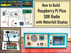 Build a Raspberry Pi Pico SDR Radio with Waterfall Display
Software-defined radio (SDR) is a radio communication system where components that have traditional...
-
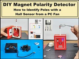 DIY Magnet Polarity Detector - How to Identify Poles with a Hall Sensor from a PC Fan
Recently, while working on a project, I needed to determine the polarity of several permanent magne...
-
 Light Meter Project - Making Dfrobot Unihiker K10 Work with Standard Arduino Libraries
The other day I received a shipment with a UNIHIKER K10 development board from DFRobot, which I rec...
-
-
mammoth-3D SLM Voron Toolhead – Manual Drill & Tap Edition
140 0 0 -
-
AEL-2011 Power Supply Module
654 0 2 -
AEL-2011 50W Power Amplifier
567 0 2 -
-
-
Custom Mechanical Keyboard
769 0 0 -
Tester for Touch Screen Digitizer without using microcontroller
395 2 2 -
Audio reactive glow LED wristband/bracelet with NFC / RFID-Tags
364 0 1 -
-


