
|
KiCADKicad
|
Electronic Timer
The proposed application will result in a general purpose programmable timer with output on a power relay. At the base of the circuit is the NE555 integrated circuit. The relay is operated when the START button is pressed and returns to the initial state after the delay time. The state of reset can be "forced" at any time by pressing the STOP button. The NE555 circuit is in configuration flip-flop-circuit; it can be seen as a flip-flop type flip-flop R-S; its inputs are pins 6 which represent the reset and 2 which is the set. The circuit also contains two comparators that lead the inputs from 6 and 2 and an output amplifier. Reset pin or "zeroing", is permanently connected to 12V (1 logic) and the operation of NE555 can be reset if pin 4 is connected to ground via the STOP button.
The delay time is: t = 1.1xRC where R = R3 + RV1, and C = C1. If R is in MOhm and C in uF, it follows that time is measured in seconds.
Example: R3 + RV1 = 1MOhm and C1 = 10uF: 1.1x1x10 = 11s
The delay time depends on RV1, it being the adjustment element of circuit, along with C1. As a result of pressing the STOP button on during a timing cycle, a new cycle can only be resumed pressing the START button again.
Some suggestions for choosing RV1 and C1: 2.5MOhm + 100uF = [110ms to 5min];
10MOhm + 47uF = [110ms to 9min]; 10MOhm + 100uF = [110ms to 19min].
It is noted the maintenance of the minimum value and a maximum possible value of 19s. Keep in mind the tolerances of components.
If the load is for AC, it is recommended that an RC series group be mounted on the relay contacts (R = 100Ohm / 1W and C = 220nF / 400Vac).
This circuit can be powered by 12V 200-500mA.
Note: The 3D model preview is just for aspect.
Electronic Timer
*PCBWay community is a sharing platform. We are not responsible for any design issues and parameter issues (board thickness, surface finish, etc.) you choose.
- Comments(0)
- Likes(0)
- 0 USER VOTES
- YOUR VOTE 0.00 0.00
- 1
- 2
- 3
- 4
- 5
- 6
- 7
- 8
- 9
- 10
- 1
- 2
- 3
- 4
- 5
- 6
- 7
- 8
- 9
- 10
- 1
- 2
- 3
- 4
- 5
- 6
- 7
- 8
- 9
- 10
- 1
- 2
- 3
- 4
- 5
- 6
- 7
- 8
- 9
- 10
 More by cris 🙂
-
 Dynamic decoration with LEDs and more
Hello everyone!As you can see in the title, we have a circuit with LEDs, many LEDs, it's a 4x4 LEDs ...
-
 LEDs Stars
Hello everyone! I'm signing up for this competition with a small project designed to attract your a...
-
 Audio amplifier with LM386 (and BASS boost)
Hello everyone!Circuit descriptionThe LM386 is quite a ve...
Audio amplifier with LM386 (and BASS boost)
Audio amplifier with LM386 (and BASS boost)Hello everyone!Circuit descriptionThe LM386 is quite a ve...
-
 Audio amplifier 25W TDA2030
A fairly well-known and interesting montagePresentationThe presented audi...
Audio amplifier 25W TDA2030
Audio amplifier 25W TDA2030A fairly well-known and interesting montagePresentationThe presented audi...
-
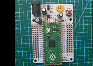 Raspberry Pi Pico Expansion Board
Hello everyone!UPDATE!!!I made some changes, routing in particular, and freed up the board of a few ...
-
 Adjustable voltage power supply
Among the most important electronic devices in the electronics laboratory is the voltage source. Thi...
-
 Digital Clock with AT89C2051
Circuit OperationShort SW2 presses cycle through displaying the current time in HH:MM and MM:SS form...
-
 Switch based light sensor
Hi!The circuit shown can be used to turn on the light in the garden, or some light panels / advertis...
-
 LM3909 flashing indicator
I present to you a circuit which is a little outdated, but quite pleasant for some, I saw that this ...
-
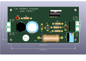 A DIY charger for 12V battery
Hello everyone!I present to you a project that really didn't reach its final state, until recently. ...
-
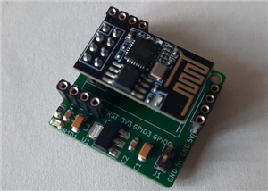 ESP01 board
Hello PCBWayers!You probably know that ESP01S/01 boards can be a little difficult to use in an easie...
-
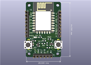 ESP12F Board
Hello makers!Some time ago I had a shopping coupon and I thought about making some simple PCBs with ...
-
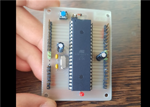 ATMega32 Board
Hi !I remembered this simple project I made for myself, you can use it with an ATMega32 or ATMega16 ...
-
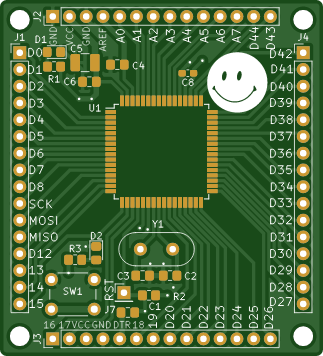 AT90CAN128
Hello makers!Here is a guy who likes to build various, small, electronic circuits, and through this ...
-
 PCBWay 11th Badge Design
Hello PCBwayers!I'm here to participate in the PCBWay 11th Badge Design Contest and after a few idea...
-
 The use of IoT technology for monitoring specific electrical parameters of autonomous power systems
Hello everyone!A brief introduction of this project.What you see presented here is a home made (or D...
-
 ESP32 Expansion Board
Expansion board for ESP32Hello everyone!This is my new PCB design. I wanted to share it with you on ...
-
 4 Digits 7 Segments CC Display Module with 74HC595
Hello! This time I want to present an 7-segment four digit display controlled by two 74HC595.The LED...
-
-
AEL-2011 Power Supply Module
524 0 2 -
AEL-2011 50W Power Amplifier
485 0 2 -
-
-
Custom Mechanical Keyboard
693 0 0 -
Tester for Touch Screen Digitizer without using microcontroller
329 2 2 -
Audio reactive glow LED wristband/bracelet with NFC / RFID-Tags
310 0 1 -
-
-


