|
|
ATMEGA8A-AUMICROCHIP(美国微芯)
|
x 1 |

|
KiCADKicad
|
|

|
arduino IDEArduino
|
|

|
TinkerCad |
LEDs Stars
Hello everyone! 👋
I'm signing up for this competition with a small project designed to attract your attention (if it really can do that 😆 to adults, rather to children), like the stars in the sky. This project that I named "My Galaxy" is the result of some attempts that date back some time, but I will talk about it during the presentation.
In short, the list of components is something like this:
- 1 card with ATMega8AU-TH;
- 4 rings with WS2812B LEDs;
- 1 IR detector module;
- 1 push button;
- 1 power switch;
- 1 DC jack;
- 5V power supply.
I no longer count hand tools, soldering iron or wires.
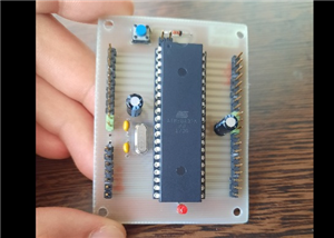
For some time I wanted to make simple board versions with ATMega uC, even if I don't make them in small sizes like the Arduino Nano, I wanted to have a board containing only uC and pin headers. Why? Because I need to have quantity, and the constructions are advantageous to me.
This particular board contains an ATMega8AU-TH, I bought several pieces cheaply from a well-known source. 😁
I made a PCB in KiCAD, later I multiplied it. It's not a grade 10 PCB, but I'm satisfied. I also had an adaptation problem, I found a promotion for the manufacture of PCBs, and I tried to import the project on an online platform, in order to later place the order with the manufacturer, only that the import was performed incorrectly, I did not realize it , and when I received the PCBs I noticed (not at first glance) that the top-bottom GND plan is not interconnected, and that's it. In the end, I did the top-bottom interconnection manually.
You can find the PCB below. I must mention that D1, C8, R2, D2 are no longer needed for this version. The board is in two layers, with dimensions of 40*50mm. Initially I started with only TH components, and I kept the proportions, but later I also added some SMDs. I know that it's a rather robust board, and about twice as big as an Arduino Nano, but it's still useful for me.
I tried to program uC in 2 ways. The first way was with FTDI programmer, but I didn't succeed, I tried to upload a bootloader in this uC but I didn't succeed and I tried various methods, still without results. I have previously done this with an ATMega8 DIP version, I think it is an ATMega8A-PU. What do I do in this case? This was the only method I had tried, until I found another source of information, this guy uses an AVR USBASP Programmer (thank you for this), and I think hmm, interesting, I think I have something like that through THAT BOX! I have collected some things that I keep in boxes, sometimes I forget if I have something or not and I buy it again, then I find it 😆.
I installed the driver to be able to use AVR USBASP and I get to work.
So, the programming method is like this: after identifying the pins, I make the connections between the programmer and uC. In my case I use ATMega8AU-TH, and I can use this diagram to recognize the pins:

I have a 10-pin plug on the board.

These are simple connections, just use jump wires and that's it.

In the Arduino IDE we must make these settings:
- select the board

- select the programmer

- and upload the code.

Maybe all this information will be useful to someone else. ︎
Now let's talk about the program. I'm not a very handy programmer, but I like it, and I kept turning to various forums (thanks for that) to bring the program in this form. How does this work? Well, the way I thought, I said to have two switches, one IR detector (or something without direct contact) and the other a simple push button. The initial state is when all LEDs are Off, and a trigger is expected. When the IR sensor is triggered, the LEDs start to light up for a certain period, about 30s, that's how long I calculated it takes for all the LEDs to light up. I called it "Short event". Instead, if I press the push button, then the LEDs light up continuously, I named it "Long event". To stop them, I have to press the push button once more. From this point of view, I must say that the program must be improved because there are some "moments" that do not happen as I would like, the transition from one event to another still has mistakes. An idea would have been to use a PIR switch instead of the sensor, or to add an LDR, so in the program I could set the LEDs to turn on in the dark and maybe I could also adjust the light intensity. There is plenty of room for improvement.
The galaxy of stars is multi-colored and different: I have 1 ring with 12 LEDs, 1 LED lights up, clockwise and counterclockwise; in the middle I have 2 rings with 8 LEDs each, I inserted them and one LED lights up one after the other; and the last ring lights up 1 LED each, forming a wheel. Unfortunately, I didn't have bigger rings, or segments of LEDs with which to build even bigger rings, so I could say that this version is rather compact, and I used what I already had at hand.
The full program is available in the download section.
If you are wondering what are all these lines of the type lastButtonState = currentButtonState or variables that contain "State", well, it's because that's how I managed to do button debounce for the push button, and I applied the same principle to the IR sensor. Playing with LEDs may seem a bit complicated, but I tried to put all this in a function called Wsb().
I have libraries, global variables, in setup() there are some initializations. In loop(), it starts with detecting the state of the switches (mainly), and checks are made. Through the two switches I made a short menu, menu1 = 1, basically, triggering the IR sensor produces a single activity, namely lighting the LEDs for 30s, after which they turn off by themselves. Pressing the push button for the first time leads to menu2=1, the LEDs light up permanently, and to turn them off I have to enter menu2=2, pressing the push button.
Moving to 3D printing.
The model in which the rings are placed is inspired, but I like their placement, and since it was not easy for me to make this model for the rings using cardboard or something similar, I said to try something 3D printed. I have no knowledge at all, so I checked YouTube (😆) and chose Tinkercad, I work online, and for simpler things it's enough. I use many individual shapes, which I later combine into a single piece..


I found a 3D printer in town, very good so far. But, with all my enthusiasm, I started with many mistakes, until I made this 3D these piece, I had 3 attempts, and I made mistakes like either not leaving more generous tolerances to fit the pieces, or thicknesses, or because of the white material something happens and the piece had spots, something brown like a burn (you can also see it on the last piece). Then I thought about how thick the piece should be in the area where the LEDs light up, and in the end I have 1.2mm, I have to give the piece some rigidity. The piece didn't come out with round edges because I didn't use what was needed in Tinkercad. It is more cultured but it is resistant.
The box in which I placed all the pieces is at the limit of its dimensions, another thing to improve in the future, and hence quite a lot of time spent to be able to do something to fit the pieces. I have to file the switch and the DC plug because they are very close (I can't even mount the nut on the DC plug anymore 😟). Besides, I have to use a file for all the parts (😂😅) because the holes were not right, and no, I didn't have much inspiration when placing and holding the parts in the boxes, so I had to use adhesive tape and a little glue Using two screws and nuts I attached the base rings. The part with the rings is slightly deformed at the base, but I was able to fit it, but I happened to break a drill bit in the box (at the base), and now I can no longer mount the fourth screw. I have to find a way to remove that broken drill bit.
Soldering the wires was a long job, because (again, my mistake) I left a small space, and a bit cramped, but using tweezers to grab those thin wires I somehow managed to solder them. I made a few holes in the pieces through which I passed the wires.
For the whole project I use a single 5V power supply, which means it's very convenient, I just need the DC plug to fit.
Take a look at what came out. 😁👍


I also leave a short video, that's the only way to see it best. ✔
https://youtube.com/shorts/byI-oUrSXMg?feature=share
This is all for today. Thank you and have a nice day!
References:
AVR USB driver: https://zadig.akeo.ie/
How to use the AVR USB programmer: https://www.youtube.com/watch?v=ToKerwRR-70&list=PLT_xFb7a1cCS6954C9E3Q8SskbZ38J2vB&index=5&t=405s&ab_channel=ZeroAmpsElectronics
ATMega8 pinout: https://www.google.com/url?sa=i&url=https%3A%2F%2Fwww.pinnaxis.com%2F%3Fk%3Dsmd-atmega8a-same-as-atmega328-microcontrollers-arduino-forum-ee-On9kwjFe&psig=AOvVaw2sQPJQNAJhBbb8cRUzrWvK&ust=1718814906707000&source=images&cd=vfe&opi=89978449&ved=2ahUKEwjmm-7QyuWGAxXPk_0HHT1_DrgQjRx6BAgAEBQ

LEDs Stars
*PCBWay community is a sharing platform. We are not responsible for any design issues and parameter issues (board thickness, surface finish, etc.) you choose.
- Comments(0)
- Likes(2)
-
 rachman bobo
Dec 18,2024
-
 cris 🙂
Nov 02,2024
- 0 USER VOTES
- YOUR VOTE 0.00 0.00
- 1
- 2
- 3
- 4
- 5
- 6
- 7
- 8
- 9
- 10
- 1
- 2
- 3
- 4
- 5
- 6
- 7
- 8
- 9
- 10
- 1
- 2
- 3
- 4
- 5
- 6
- 7
- 8
- 9
- 10
- 1
- 2
- 3
- 4
- 5
- 6
- 7
- 8
- 9
- 10
 More by cris 🙂
-
 Dynamic decoration with LEDs and more
Hello everyone!As you can see in the title, we have a circuit with LEDs, many LEDs, it's a 4x4 LEDs ...
-
 LEDs Stars
Hello everyone! I'm signing up for this competition with a small project designed to attract your a...
-
 Audio amplifier with LM386 (and BASS boost)
Hello everyone!Circuit descriptionThe LM386 is quite a ve...
Audio amplifier with LM386 (and BASS boost)
Audio amplifier with LM386 (and BASS boost)Hello everyone!Circuit descriptionThe LM386 is quite a ve...
-
 Audio amplifier 25W TDA2030
A fairly well-known and interesting montagePresentationThe presented audi...
Audio amplifier 25W TDA2030
Audio amplifier 25W TDA2030A fairly well-known and interesting montagePresentationThe presented audi...
-
 Raspberry Pi Pico Expansion Board
Hello everyone!UPDATE!!!I made some changes, routing in particular, and freed up the board of a few ...
-
 Adjustable voltage power supply
Among the most important electronic devices in the electronics laboratory is the voltage source. Thi...
-
 Digital Clock with AT89C2051
Circuit OperationShort SW2 presses cycle through displaying the current time in HH:MM and MM:SS form...
-
 Switch based light sensor
Hi!The circuit shown can be used to turn on the light in the garden, or some light panels / advertis...
-
 LM3909 flashing indicator
I present to you a circuit which is a little outdated, but quite pleasant for some, I saw that this ...
-
 A DIY charger for 12V battery
Hello everyone!I present to you a project that really didn't reach its final state, until recently. ...
-
 ESP01 board
Hello PCBWayers!You probably know that ESP01S/01 boards can be a little difficult to use in an easie...
-
 ESP12F Board
Hello makers!Some time ago I had a shopping coupon and I thought about making some simple PCBs with ...
-
 ATMega32 Board
Hi !I remembered this simple project I made for myself, you can use it with an ATMega32 or ATMega16 ...
-
 AT90CAN128
Hello makers!Here is a guy who likes to build various, small, electronic circuits, and through this ...
-
 PCBWay 11th Badge Design
Hello PCBwayers!I'm here to participate in the PCBWay 11th Badge Design Contest and after a few idea...
-
 The use of IoT technology for monitoring specific electrical parameters of autonomous power systems
Hello everyone!A brief introduction of this project.What you see presented here is a home made (or D...
-
 ESP32 Expansion Board
Expansion board for ESP32Hello everyone!This is my new PCB design. I wanted to share it with you on ...
-
 4 Digits 7 Segments CC Display Module with 74HC595
Hello! This time I want to present an 7-segment four digit display controlled by two 74HC595.The LED...
-
-
AEL-2011 Power Supply Module
553 0 2 -
AEL-2011 50W Power Amplifier
512 0 2 -
-
-
Custom Mechanical Keyboard
710 0 0 -
Tester for Touch Screen Digitizer without using microcontroller
340 2 2 -
Audio reactive glow LED wristband/bracelet with NFC / RFID-Tags
321 0 1 -
-
-


