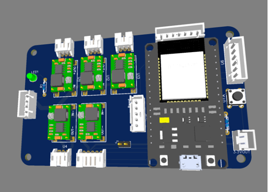
Manipulator PCB
Welcome to the Homemade Manipulator Arm project repository! This project features a DIY robotic arm with 6 degrees of freedom (6DoF) and a gripper. The arm is controlled using 4 MG1501 servos and 3 SG90 servos. The project includes SolidWorks 3D part designs, electrical schemas created with EasyEDA, and the ESP code for controlling the arm. Use PlatformIO in Visual Studio Code (VSCode) to manage and upload the code to the ESP microcontroller.


Contents
Description
Components
Folder Structure
Usage
Credits
Sponsors
License
Description
This project is a homemade manipulator arm designed for educational purposes and hobbyist robotics enthusiasts. The arm is built using 3D-printed parts designed in SolidWorks and controlled using ESP32 microcontroller boards. The control methods include Bluetooth Low Energy (BLE) using the RemoteXY library or manual control using encoders (potentiometers).
The kinematics of the manipulator are represented using the Denavit-Hartenberg (DH) notation as follows:
Linkaα (deg)dθ (deg)009094.85901104009021040003090-7.659040-9066.6050066.60
a_i: Represents the link length along the (x_i) axis.
α_i: Represents the twist angle about the (x_i) axis in degrees.
d_i: Represents the link offset along the (z_{i-1}) axis.
θ_i: Represents the joint angle about the (z_{i-1}) axis in degrees.
Components
The manipulator arm features the following components:
Servos:
4 x MG1501 servos (for joints)
3 x SG90 servos (for gripper and the last wrists)
Electronics:
ESP32 microcontroller board
PCB Board to control the robot
PCB Board with Potentiometers (for manual control using encoders)
3D Parts:
Various parts designed in SolidWorks for the arm's structure
Electrical Schemas:
Schemas created in EasyEDA for the wiring and electronic components layout
Full BOM can be found:
For Manipulator
For Potentiometers
Folder Structure
The repository is organized as follows:
/Code
├── src/main.cpp # Main file of the Project
├── lib # Folder containing help libraries
/Cad
├── stl # Folder with stl files for 3D
├── *.sldprt # SolidWorks files printing
/Electrical_Schemas
├── Main Board # Electrical schemas created in EasyEDA for the robot control PCB
├── Potentiometer Board # Electrical schemas created in EasyEDA for the Potentiometer PCB
/docs # Datasheets for some of the components
/robodk # Robodk station with the robot. Note: The movement of the manipulator in robodk is not exactly the same due to robodk mechanism build limitations.
/README.md
Usage
To replicate or modify this project, follow these steps:
3D Printing:
Print the 3D parts from the \Cad\stl directory using a 3D printer
Assembly:
Assemble the printed parts and servos according to the design
Electronics:
Choose one of the following methods:
Option 1: Order PCB Boards:
Use the provided PCB design files (*.zip) in the repository's attachments to order custom PCB boards.
- Manipulator Main PCB
- Potentiometer PCB
Option 2: Manual Wiring:
Refer to the electrical schemas (Electrical_Schemas) and wire up the servos, microcontroller, and other components manually based on the schematic PDFs (*.pdf).
- Manipulator Main Scheme
- Potentiometer Scheme
Programming:
Use PlatformIO in Visual Studio Code (VSCode) to manage and upload the code
Control:
Use the RemoteXY library for BLE control, or wire up potentiometers for manual control
Manipulator PCB
*PCBWay community is a sharing platform. We are not responsible for any design issues and parameter issues (board thickness, surface finish, etc.) you choose.
- Comments(0)
- Likes(0)
- 0 USER VOTES
- YOUR VOTE 0.00 0.00
- 1
- 2
- 3
- 4
- 5
- 6
- 7
- 8
- 9
- 10
- 1
- 2
- 3
- 4
- 5
- 6
- 7
- 8
- 9
- 10
- 1
- 2
- 3
- 4
- 5
- 6
- 7
- 8
- 9
- 10
- 1
- 2
- 3
- 4
- 5
- 6
- 7
- 8
- 9
- 10
 More by Tamir Mhabary
-
-
AEL-2011 Power Supply Module
553 0 2 -
AEL-2011 50W Power Amplifier
512 0 2 -
-
-
Custom Mechanical Keyboard
710 0 0 -
Tester for Touch Screen Digitizer without using microcontroller
340 2 2 -
Audio reactive glow LED wristband/bracelet with NFC / RFID-Tags
322 0 1 -
-
-


