Nixie Thermometer / Hygrometer IN-14, ИН-14
Nixie Thermometer / Hygrometer
Tubes, sensors and a micro in a single design
Nixie Thermometer / Hygrometer
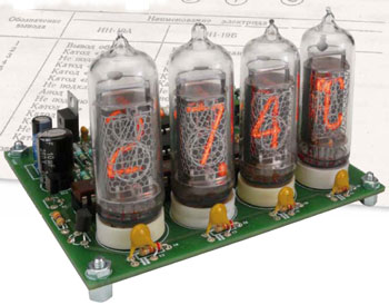
Measuring temperature and humidity with a modern sensor and displaying the values on a retro display — it’s all described in this article. A calibrated, ‘digital’ sensor provides data via its I2C interface to a microcontroller driving four Nixie tubes and automatically alternating between temperature and humidity, while providing a nice fading effect. It’s a must-have!
Component list
Resistors
R1-R4 = 22kOhm
R5,R11,R12 = 10kOhm
R7 = 47kOhm
R8 = not used
R9 = 820kOhm
R10 = 330(
R13 = 5.6kOhm
R14 = 470kOhm
R15 = 4.7kOhm
R16 = 150(
Capacitors
C1-C4 = 100pF 2000V, 10%, radial, 5mm pitch (Farnell #1141797)
C5-C8,C11,C12,C16-C18 = 100nF 50V, 20%, pitch 5mm
C9, C10 = 33pF 100V, 5%, 2.54mm pitch
C13 = 10μF 250V, 20%, radial, 5mm pitch
C14,C15 = 100μF 25V, 20%, radial, 2.5mm pitch
C19 = 470pF, 100V, 10%, 5mm pitch
Inductors
L1 = 330μH 1A, 20%, axial, D×L = 11×32.5 mm (0.43”×1.28”) max.
Semiconductors
D1 = BYV26
D2-D4 = 1N4001
IC1-IC4 = 74141 or K155ID1 (?155??1)
IC5 = PIC16F876-20/SP
IC6 = 7805
IC7 = MC34063
IC8 = SHT21 I2C humidity and temperature sensor [1] (Farnell #1855468)
T1,T2 = MPSA42
T3 = IRF820
Miscellaneous
X1 = 6MHz quartz crystal
V1 = IN-19A, Nixie Tube (symbols)
V2-V4 = IN-14, Nixie Tube (numeric)
K1 = 2-way PCB terminal block, 5mm pitch
PCB # 110321-1
As you can see from the following pictures, the project progressed nicely…
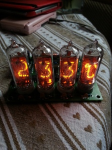
This picture shows the top view, without the last tube, which I was waiting for
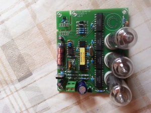
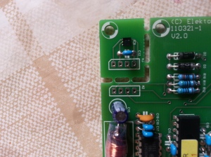
Most of the components are very easy to solder on. The Nixie tubes are very hard to get into the holes, but I managed it so anyone should be able to do it! However, the Sensirion SHT21 chip is 3mm x 3mm and is ridiculously hard to get on – this needs specialist attention and a steady hand. You can see the sensor in place in the picture below. Be sure to read the data sheet correctly, and don’t solder it on the wrong way (I *may* have done this!)
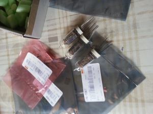
The tubes eventually turned up – I was more excited than I probably should have been ??
Finally the final tube came and was soldered into place – a really lovely display. The sensor has to be at least 15cms from the circuit board, otherwise you get spurious results from the heat of the components on the board
I built this case to house it, Im very very pleased with it
Nixie Thermometer / Hygrometer IN-14, ИН-14
*PCBWay community is a sharing platform. We are not responsible for any design issues and parameter issues (board thickness, surface finish, etc.) you choose.
- Comments(0)
- Likes(3)
-
 rogeros
Jun 13,2023
-
 Engineer
Jun 03,2023
-
 Alexey Sheglov
Apr 22,2021
- 0 USER VOTES
- YOUR VOTE 0.00 0.00
- 1
- 2
- 3
- 4
- 5
- 6
- 7
- 8
- 9
- 10
- 1
- 2
- 3
- 4
- 5
- 6
- 7
- 8
- 9
- 10
- 1
- 2
- 3
- 4
- 5
- 6
- 7
- 8
- 9
- 10
- 1
- 2
- 3
- 4
- 5
- 6
- 7
- 8
- 9
- 10
 More by fxw451
-
 Nixie Thermometer / Hygrometer IN-14, ИН-14
Nixie Thermometer / HygrometerTubes, sensors and a micro in a single designNixie Thermometer / Hygro...
-
 Nixie Tube Thermometer in-16
Nixie Tube ThermometerRetro temperature displayNixie Tube ThermometerIn this article we describe the...
-
 DIY Metcal 13.56 MHz RF Supply - Controller
DIY Metcal 13.56 MHz RF Supplyhttps://www.eevblog.com/forum/projects/diy-metcal-13-56-mhz-rf-supply/...
-
-
mammoth-3D SLM Voron Toolhead – Manual Drill & Tap Edition
211 0 0 -
-
AEL-2011 Power Supply Module
735 0 2 -
AEL-2011 50W Power Amplifier
608 0 2 -
-
-
Custom Mechanical Keyboard
813 0 0 -
Tester for Touch Screen Digitizer without using microcontroller
440 2 2 -
Audio reactive glow LED wristband/bracelet with NFC / RFID-Tags
392 0 1 -
-


