Power Supply +24v GND -9V
ENG - This project is a stabilized power supply with 2x15v input with +27V and -9V outputs.
This is the Power supply stage for the Phono Preamp called inDiscreto.
Free DIY project by TNT-Audio
Author: Giorgio Pozzoli - TNT Italia
Published: March, 2003
ITA - Alimentatore stabilizzato con ingresso 2x15v ed uscite a +27V e -9V.
Questo progetto è ricavato dall'alimentatore utilizzato per il Preamplificatore Phono chiamato inDiscreto.
Progetto fai da te gratuito di TNT-Audio
Autore: Giorgio Pozzoli - TNT Italia
Pubblicato: Marzo, 2003
ENG
CIRCUIT DESCRIPTION
The first regulator is a simple MOSFET capacitance multiplier. the voltage on the MOSFET gate is kept practically fixed by an RC filter (C6-C8-R5 and C7-C9-R6) with a very high time constant (respectively 220sec and 470sec: it takes 20 and 40 minutes to reach 95% of the final voltage...). The output voltage is determined by the voltage divider (R1-R2 and R3-R4).
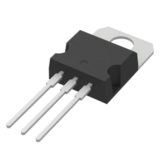
Both N-channel and P-channel power mosfets IRF630 and IRF9630 were used - but almost all power mosfets of the same channel type are suitable. Note R7 and R8: they represent "gate stoppers", they are resistors to be connected as close as possible to the gate in order to eliminate any possible self-oscillation. If you hear background noise, move the resistors towards the gate pin and/or increase their value.
The second regulator is based on a common (at least in the audio field) "shunt regulator" integrated circuit, the TL431. Its characteristics are very similar, as well as the symbol used, to a programmable precision zener; its dynamic impedance is of the order of 0.2ohm!
The integrated circuit works in such a way that the voltage between the anode (the lowest terminal in the diagram) and the reference (the central connection which has a very high impedance) cannot be greater than 2.5V. The current in the resistance (R12 and R14) placed between these two points is therefore fixed, and it is possible to program the "zener voltage" simply by inserting a further resistance (R11 and R13) between the reference and the cathode: the formula for the voltage calculation Vreg is as follows:
Vreg = ( 1 + R11 / R12 ) * 2.5v
An additional resistor (R9 and R10) is needed to create a difference between the input and regulated voltage; pay attention in order to be sure that the current flowing in the integrated circuit is sufficient without exceeding the limit value of power dissipation.
With such a double setting there is no risk of ripple from the power supply reaching the phono stage!
ITA
DESCRIZIONE DEL CIRCUITO
Il primo regolatore è un semplice moltiplicatore di capacità realizzato a MOSFET. la tensione sul gate del MOSFET è mantenuta praticamente fissa da un filtro RC (C6-C8-R5 e C7-C9-R6) con una costante di tempo molto elevata (rispettivamente 220sec e 470sec: impiega 20 e 40 minuti per raggiungere il 95% della tensione finale...). La tensione di uscita è determinata dal divisore di tensione (R1-R2 e R3-R4).
Sono stati utilizzati i mosfet di potenza IRF630 e IRF9630 a canale N e a canale P - ma quasi tutti i mosfet di potenza dello stesso tipo di canale sono adatti. Notate R7 e R8: rappresentano dei "gate stoppers", sono resistenze da collegare il più vicino possibile al gate al fine di eliminare qualsiasi possibile auto oscillazione. Nel caso in cui doveste sentire un rumore di fondo, spostate le resistenze verso il piedino del gate e/o aumentate il valore delle stesse.
Il secondo regolatore è basato su un comune (almeno in campo audio) circuito integrato "shunt regulator", il TL431. Le sue caratteristiche sono molto simili, così come il simbolo utilizzato, ad uno zener di precisione programmabile; la sua impedenza dinamica è dell'ordine dei 0.2ohm!
Il circuito integrato funziona in modo tale che la tensione tra l'anodo (il terminale più in basso nello schema) ed il riferimento (la connessione centrale che presenta un'impedenza molto alta) non possa essere maggiore di 2.5V. La corrente nella resistenza (R12 e R14) messa tra questi due punti è quindi fissa , ed è possibile programmare la "tensione di zener" semplicemente inserendo un'ulteriore resistenza (R11 e R13) tra il riferimento ed il catodo: la formula per il calcolo della tensione Vreg è la seguente:
Vreg = ( 1 + R11 / R12 ) * 2.5v
È necessaria un'ulteriore resistenza (R9 e R10) per creare una differenza tra la tensione d'ingresso e quella regolata; prestate attenzione al fine di essere sicuri che la corrente che scorre nel circuito integrato sia sufficiente senza però superare il valore limite della dissipazione di potenza.
Con una doppia regolazione siffatta non si corre il rischio che i ripple provenienti dall'alimentazione arrivino allo stadio phono!
Power Supply +24v GND -9V
*PCBWay community is a sharing platform. We are not responsible for any design issues and parameter issues (board thickness, surface finish, etc.) you choose.
- Comments(0)
- Likes(1)
-
 Marc Porté Roca
Apr 17,2025
- 0 USER VOTES
- YOUR VOTE 0.00 0.00
- 1
- 2
- 3
- 4
- 5
- 6
- 7
- 8
- 9
- 10
- 1
- 2
- 3
- 4
- 5
- 6
- 7
- 8
- 9
- 10
- 1
- 2
- 3
- 4
- 5
- 6
- 7
- 8
- 9
- 10
- 1
- 2
- 3
- 4
- 5
- 6
- 7
- 8
- 9
- 10
 More by Giancarlo Madonna
-
-
mammoth-3D SLM Voron Toolhead – Manual Drill & Tap Edition
251 0 0 -
-
AEL-2011 Power Supply Module
776 0 2 -
AEL-2011 50W Power Amplifier
643 0 2 -
-
-
Custom Mechanical Keyboard
838 0 0 -
Tester for Touch Screen Digitizer without using microcontroller
460 2 2 -
Audio reactive glow LED wristband/bracelet with NFC / RFID-Tags
407 0 1 -
-


