Stanley A Meyer Doubled E Core Bobbin Choke Ballast
Stanley A Meyer Doubled E Core Bobbin Choke Ballast E core Case 8XA 9XA
JOIN US HERE
LEARN EVERYTHING BE A GLOBAL MASTER WITH US
NANO BUBBLEWATER FUEL
https://www.patreon.com/c/securesupplies/shop
Stanley A. Meyer’s water fuel cell system relies on a unique dual-choke, bifilar-wound ballast design as part of his Voltage Intensifier Circuit (VIC). This setup is crucial for creating the high-voltage, high-frequency pulses necessary to produce “nano-bubble” water fuel. Here’s a breakdown of the purpose, structure, and functionality of the dual choke, bifilar-wound ballast in Meyer’s VIC:
1. Purpose of the Dual Choke in Stanley Meyer’s VIC
The dual choke serves several key purposes in Meyer’s water fuel system:
Voltage Amplification and Isolation: The chokes help increase voltage by acting as inductors, while also isolating the high-voltage pulse from the main power supply, preventing current from directly reaching the water fuel cell. This supports Meyer’s claim that his water splitting method requires high voltage and low current.
Pulse Timing and Control: The chokes work in tandem with the VIC to control the timing of voltage pulses. These controlled pulses are crucial for achieving resonance in the water fuel cell, which allows for efficient energy transfer and enhanced water molecule dissociation.
Restricting Current Flow: The chokes limit the current in the system. Since Meyer’s method relies on maintaining high voltage with low current, the chokes help prevent excess current that could disrupt the resonance and cause inefficient water splitting.
2. Structure and Design of the Dual Bifilar-Wound Choke
The dual choke used in Meyer’s VIC is bifilar-wound, meaning that two wires are wound together on the same core in parallel. Here’s why this is significant:
Bifilar Winding: In a bifilar-wound coil, two wires are wound together in a way that allows magnetic fields from each wire to interact. This creates mutual inductance, which amplifies the voltage across the coil, enhancing the VIC's ability to produce the required high-voltage pulses.
Choke Pairing: Meyer’s setup typically uses two chokes wound in parallel, sometimes with opposite polarities. This setup generates a balanced electromagnetic field, effectively increasing inductance while reducing unwanted reactive effects. It also helps produce a phase-shifted pulse in the secondary winding.
Core Material: The chokes are usually wound around a ferrite or laminated core. Ferrite cores are preferred for high-frequency applications due to their low eddy current losses. Meyer’s choice of core material would aim to maximize inductive coupling without excessive energy loss.
3. Working Mechanism of the Dual Choke in the Water Fuel Cell
The dual choke operates as follows:
Step 1: High-Voltage Pulse Creation: When a pulse from the VIC is applied, the chokes create a high-voltage field across the water fuel cell. The bifilar winding enhances the inductive voltage, leading to an intense electric field.
Step 2: Restricting Current (High Voltage, Low Current): The chokes create an impedance that restricts current, keeping it within Meyer’s specifications of high voltage and low current. This restriction helps maintain the necessary conditions for nano-bubble production in the water fuel cell.
Step 3: Resonance and Voltage Amplification: As the system reaches resonance, the chokes enhance the voltage even further, amplifying the energy applied to the water molecules. The goal is to achieve resonance at a specific frequency that aligns with the natural frequency of the water molecules, making it easier to dissociate hydrogen and oxygen.
Step 4: Creating Nano-Bubbles: The controlled high-voltage pulses create localized nano-bubbles in the water. These nano-bubbles are highly reactive and contain a mixture of hydrogen and oxygen gases. The chokes ensure that these bubbles form without causing excess current, which could disrupt the delicate resonance required for efficient gas production.
4. Technical Benefits of the Dual Bifilar-Wound Choke Design
Voltage Enhancement: The bifilar winding increases inductance and mutual coupling, allowing for higher voltage pulses.
Reduced Reactive Losses: By using chokes in a bifilar-wound configuration, reactive losses (like eddy currents) are minimized, making the system more efficient.
Improved Magnetic Field Control: The dual choke design with opposing polarities allows for better control over the magnetic field, which is crucial for stabilizing the pulse frequency and amplitude.
Efficient Nano-Bubble Production: The high voltage and restricted current work together to produce nano-bubbles without introducing large currents that could destabilize the system.
5. Additional Details on Circuit Integration
Choke Positioning in the Circuit: In Meyer’s circuit, the chokes are placed between the transformer’s secondary winding and the water fuel cell. This configuration allows the chokes to control and condition the pulse before it reaches the cell.
Duty Cycle Control: The pulse duration (duty cycle) and frequency can be adjusted to optimize resonance and nano-bubble formation. The chokes play a role in controlling this by adjusting the inductance based on the winding setup and the core’s magnetic properties.
Phase Shifting: The dual chokes, especially if wound in opposite directions, can produce a phase-shifted pulse. This phase-shifted pulse may help improve water molecule resonance and dissociation efficiency.
Conclusion
Stanley Meyer’s dual choke bifilar-wound ballast in the VIC is an innovative and integral component for nano-bubble water fuel production. By leveraging high-voltage, low-current pulses, it maximizes energy efficiency in dissociating water molecules. The dual-choke design restricts current while enhancing voltage, supporting the formation of nano-bubbles without needing high-power input. This approach not only supports Meyer’s vision of hydrogen-based fuel but also represents a unique application of resonance, inductance, and controlled pulsing in fuel cell technology.
Daniel's kind-hearted approach and dedication to a cleaner energy future deserve recognition and support.
JOIN SUPPORT LEARN MORE HERE https://www.patreon.com/c/securesupplies
You can contribute to his ongoing efforts by donating through PayPal at https://www.paypal.com/donate/?hosted_button_id=29MNNNGUSBQXW
Additionally, joining his Builder Level on Patreon at https://www.patreon.com/c/securesupplies grants you access to exclusive updates, resources, and a community of like-minded supporters dedicated to advancing hydrogen technology.
By supporting his work, you join in the journey toward a sustainable future. Godspeed, Daniel Donatelli!
Stanley A Meyer Doubled E Core Bobbin Choke Ballast
*PCBWay community is a sharing platform. We are not responsible for any design issues and parameter issues (board thickness, surface finish, etc.) you choose.
- Comments(0)
- Likes(2)
-
 (DIY) C64iSTANBUL
Nov 08,2024
-
 Daniel Donatelli
Nov 08,2024
- 0 USER VOTES
- YOUR VOTE 0.00 0.00
- 1
- 2
- 3
- 4
- 5
- 6
- 7
- 8
- 9
- 10
- 1
- 2
- 3
- 4
- 5
- 6
- 7
- 8
- 9
- 10
- 1
- 2
- 3
- 4
- 5
- 6
- 7
- 8
- 9
- 10
- 1
- 2
- 3
- 4
- 5
- 6
- 7
- 8
- 9
- 10
 More by Daniel Donatelli
-
 Stanley A Meyer VIC Voltage intensifier circuit transformer board v1.8 updated jan 11 2021
Stanley A Meyer VIC Voltage intensifier transformer board Join Support help change the World https:/...
-
 STANLEY A MEYER LES BANKI AUTO START AUTO WATER FUEL REFILL
Join Support help change the World https:...
STANLEY A MEYER LES BANKI AUTO START AUTO WATER FUEL REFILL
STANLEY A MEYER LES BANKI AUTO START AUTO WATER FUEL REFILLJoin Support help change the World https:...
-
 Stanley A Meyer Gated Pulse Frequency Generator K3 with DB 37 updated 060622
Stanley A Meyer Gated Pulse Frequency Generator K3 with DB 37 to suit matrix vic main board Join Sup...
-
 Stanley A Meyer K2 Variable Pulse Frequency Generator GMS Vic Matrix PCB Gerber
Stanley A Meyer K2 Variable Pulse Frequency Generator GMS Vic Matrix PCBGerberJoin Support help chan...
-
 Hyduino Stim Stimulator circuit board Ms EMS ECU
Join Support help change the World https://www.patre...
Hyduino Stim Stimulator circuit board Ms EMS ECU
Hyduino Stim Stimulator circuit board Ms EMS ECUJoin Support help change the World https://www.patre...
-
 Stanley A Meyer VIC Daughter Board Driver Transistor Circuit board Version 1
 Updated 28th Sept 2021 ...
Stanley A Meyer VIC Daughter Board Driver Transistor Circuit board Version 1
Stanley A Meyer VIC Daughter Board Driver Transistor Circuit board Version 1 Updated 28th Sept 2021 ...
-
 Stanley A Meyer VIC Daughter Board Driver USed with Variac EEC eleectron eextrract & chokes
Stanley A Meyer VIC Daughter Board Driver USed with Variac EEC eleectron extrract & chokes can d...
-
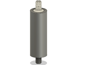 Stanley A Meyer Fuel Line Insert WFC Nano Bubble Water Fuel Cell V3
Stanley A Meyer WFC Nano Bubble Water Fuel Cell V3 Barbed Fuel Line insert Stanley a Meyer WFC Nano ...
-
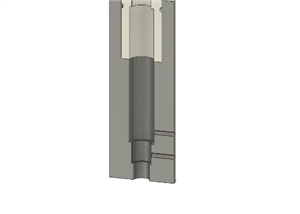 Stanley A Meyer Nano Bubble Water Fuel Cell WFC Parts 2026 V2
Stanley a Meyer WFC Nano Bubble Water Fuel Cell Single Cell 2026Stanley a Meyer Single Cell 2026This...
-
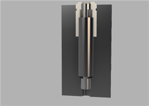 Stanley a Meyer WFC Nano Bubble Water Fuel Cell Single Cell 2026
Stanley a Meyer Single Cell 2026This is a work to make it faster easier for every one to get the cel...
-
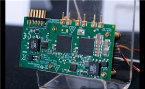 2025 Stanley A Meyer Egan Half Bridge Switch VOLTROLYSIS
Join the Builder LevelBy joining the Builder...
2025 Stanley A Meyer Egan Half Bridge Switch VOLTROLYSIS
2025 Stanley A Meyer Egan Half Bridge Switch VOLTROLYSISJoin the Builder LevelBy joining the Builder...
-
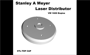 Stanley A Meyer vw 1600 Cap Laser Distributor
Video https://youtu.be/XQd8zwEA4LE?si=dpG4jgLsHhYTkX5cJ...
Stanley A Meyer vw 1600 Cap Laser Distributor
Stanley A Meyer vw 1600 Cap Laser DistributorVideo https://youtu.be/XQd8zwEA4LE?si=dpG4jgLsHhYTkX5cJ...
-
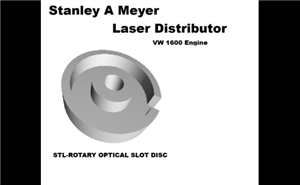 Stanley A Meyer vw 1600 STL-ROTARY OPTICAL SLOT DISC
Video https://youtu.be/XQd8zwEA4LE?si=dpG4jgLsHh...
Stanley A Meyer vw 1600 STL-ROTARY OPTICAL SLOT DISC
Stanley A Meyer vw 1600 STL-ROTARY OPTICAL SLOT DISCVideo https://youtu.be/XQd8zwEA4LE?si=dpG4jgLsHh...
-
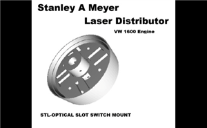 Stanley A Meyer vw 1600 STL-OPTICAL SLOT SWITCH MOUNT
Video https://youtu.be/XQd8zwEA4LE?si=dpG4jgLsH...
Stanley A Meyer vw 1600 STL-OPTICAL SLOT SWITCH MOUNT
Stanley A Meyer vw 1600 STL-OPTICAL SLOT SWITCH MOUNTVideo https://youtu.be/XQd8zwEA4LE?si=dpG4jgLsH...
-
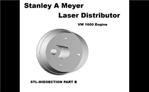 Stanley Meyer Laser VW 1600 Buggy Distributor STL-MIDSECTION PART B
Video https://youtu.be/XQd8zwEA4L...
Stanley Meyer Laser VW 1600 Buggy Distributor STL-MIDSECTION PART B
Stanley Meyer Laser VW 1600 Buggy Distributor STL-MIDSECTION PART BVideo https://youtu.be/XQd8zwEA4L...
-
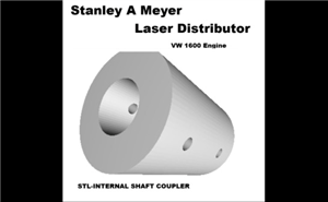 Stanley Meyer Laser VW 1600 Buggy Distributor STL-INTERNAL SHAFT COUPLER
 Video https://youtu.be/XQd8...
Stanley Meyer Laser VW 1600 Buggy Distributor STL-INTERNAL SHAFT COUPLER
Stanley Meyer Laser VW 1600 Buggy Distributor STL-INTERNAL SHAFT COUPLER Video https://youtu.be/XQd8...
-
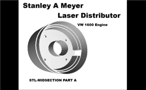 Stanley Meyer Laser VW 1600 Buggy Distributor STL-MIDSECTION PART A
Stanley Meyer Laser VW 1600 Buggy STL-MIDSECTION PART A Video https://youtu.be/XQd8zwEA4LE?si=dpG4jg...
-
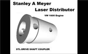 Stanley Meyer Laser VW 1600 Buggy Distributor STL-DRIVE SHAFT COUPLER (1)
Stanley Meyer Laser VW 1600 Buggy Distributor Video https://youtu.be/XQd8zwEA4LE?si=dpG4jgLsHhYTkX5c...
-
-
mammoth-3D SLM Voron Toolhead – Manual Drill & Tap Edition
252 0 0 -
-
AEL-2011 Power Supply Module
780 0 2 -
AEL-2011 50W Power Amplifier
647 0 2 -
-
-
Custom Mechanical Keyboard
841 0 0 -
Tester for Touch Screen Digitizer without using microcontroller
463 2 2 -
Audio reactive glow LED wristband/bracelet with NFC / RFID-Tags
408 0 1 -
-


