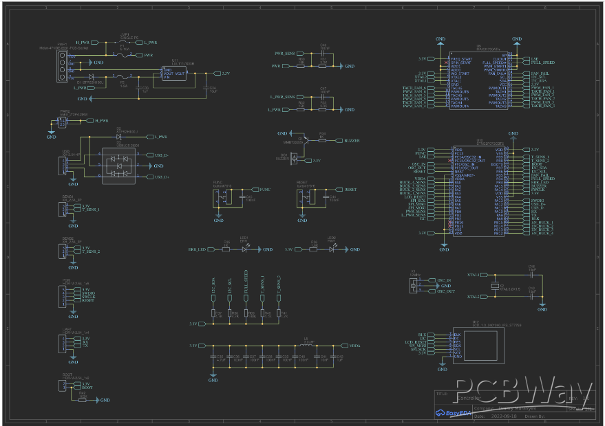
6-Channel PC Fan Controller
Introduction
The 6-Channel PC Fan Controller is a project designed to provide precise and efficient control over up to six PC cooling fans. This controller is equipped with various components to enable users to monitor and adjust fan speeds, making it ideal for optimizing system cooling and noise levels in gaming PCs, workstations, and other computing setups. The project leverages a range of electronic components, microcontrollers, and connectors to achieve its functionality.
Project Components
The project uses the following components
- Inductor (L5): A 3.3uH surface-mount inductor (SPM4020T-4R7M-LR) by TDK, used for power filtering.
- Digital Potentiometer (U1, U2, U3, U4): DS1841N+ digital potentiometers provide adjustable resistance for fan control.
- Sensor Connectors (SENS1, SENS2): XH_2.54_3P connectors for connecting temperature sensors.
- USB Connector (USB): XH-2.54-4P connector for USB communication.
- Various Capacitors (C2, C11, C19, C27, C1, C8, C9, C10, C17, C18, C25, C26, C44, C45, C46, C47, C3, C13, C21, C29, C33, C42, C34, C40, C36, C37, C38, C39, C41): Capacitors of different values for filtering and decoupling purposes.
- Voltage Regulator (U5, U6, U7, U8): ST1S41PUR voltage regulators for providing stable power.
- Crystal Oscillator (X2): XTAL-3.2X1.5 oscillator for clock timing.
- Microcontroller (U10): STM32F070CBT6 microcontroller by STMicroelectronics for controlling fan speeds and system operation.
- Fan Controllers (U9): MAX31790ATI+ fan controllers by Maxim Integrated for managing fan speeds and monitoring temperature.
- Fuse Holder (F2): 1808FUSEHOLDER for circuit protection.
- UART Connector (UART): HDR-M-2.54_1x4 connector for serial communication.
- Jumper (JMP1): JUMPER SHORT WIRE for configuration settings.
- LEDs (LED1, LED2): LED0805_GREEN indicators for power and status.
- Power Socket (PWR1): MOLEX-4P-IDE-8981-PCB-Socket for power input.
- Power Connector (PWR2): CONN-TH_55692-2P4.2MM for connecting power.
- Transistor (Q1): 2N2222 transistor for switching functions.
- Resistors (R1, R2, R3, R4, R7, R8, R11, R12, R13, R14, R21, R22, R23, R24, R27, R28, R30, R31, R32, R33, R34, R35, R36, R37, R38, R39, R40, R41, R42): Resistors of various values for voltage dividers and signal conditioning.
- Buttons (RESET, FUNC): button668 buttons for user interaction.
- Buzzer (SG1): 12mm buzzer for audible alerts.
- Voltage Regulator (U11): LDL1117S33R voltage regulator for powering the LCD.
- LCD Display (U12): 1.3-inch 240x240 IPS LCD (ST7789) for displaying information.
- Crystal Oscillator (X1): CSTCE16M0V53-R0 16MHz oscillator for system clock.
- Programming Connector (PGM): HDR-M-2.54_1X5 connector for programming and debugging.
- Fuse Holder (F1): 1808FUSEHOLDER for additional circuit protection.
- Capacitor (C35): 4.7uF capacitor for filtering.
- Fan Connectors (FAN1, FAN2, FAN3, FAN4, FAN5, FAN6): KF2510-4A connectors for connecting and controlling cooling fans.
Project Objectives
The primary objectives of the 6-Channel PC Fan Controller project are as follows
Fan Speed Control: Implement precise fan speed control for up to six fans to optimize cooling performance.
Temperature Monitoring: Incorporate temperature sensors to monitor system temperature.
User Interface: Provide user interaction through buttons and display to configure and monitor the system.
Reliable Power Supply: Ensure stable and efficient power distribution to all components.
Safety: Implement circuit protection mechanisms to safeguard against overcurrent and short circuits.
Programmability: Allow for firmware updates and configuration changes via the UART interface.
Conclusion:
The 6-Channel PC Fan Controller project aims to enhance the cooling and performance of PC systems by offering robust fan control and temperature monitoring capabilities. With a combination of electronic components and microcontroller technology, this project is designed to provide a user-friendly and efficient solution for managing PC cooling systems.
Schematic And Pcb Layout


- Comments(0)
- Likes(0)


