Robocup Jr Soccer Phoenix Team
The team
The Phoenix team of Pacinotti-Archimede’s technical institute of Rome, is composed by two groups of Italian students that focuses on designing and building Soccer robots for national and international competitions.
The initial team was founded in 2012-13 by 4 students of our school (Emanuele, Andrea, Fabio and Alessio), who succeeded in obtaining several important prizes in the course of the years, including the second place at Austrian Robocup competition in 2015.
For this year ( 2019 ), our objective is to win the first place in the RomeCup competition, as it would allow us to access the world competition in Sydney during summer.
The robot(s)
Each group of students designed two robots (total of 4), both with identical capabilities as they should be able to exchange roles (attacker and goalkeeper) during the match.
Every platform is powered by a 12V LiPo battery, which garants enough power to control the following modules:
3 Pololu 25D gearmotors for holonomic movement
Kicker
Dribbler (one more gearmotor)
Pixy camera for object recognition
HC-05 Bluetooth module
BNO055 IMU for orientation and position estimation
Line detection modules

Many of the robot parts are built with the aid of 3D Printers. For instances, in order to achieve holonomic movement, special wheels have to be designed, which garants no friction on two axes. These wheels have been designed and produced by Us, at our school, using a Zortrax 3D Printer.
Talking about Bluetooth module, it’s purpose is to guarantee a way of communication between the robots, on which critical information can be exchanged (like ball track loss, or robot eliminated from field).
All the technical details are to be found in our github repositories:
More about differences in both designs will be discussed in the next section.
Circuit Boards
We designed multiple circuit boards to be mounted on the platforms, taking into account their lightness and reliability.
Each group decided to take a different path in many ways. Let’s analyze them !
Valepercy’s platform
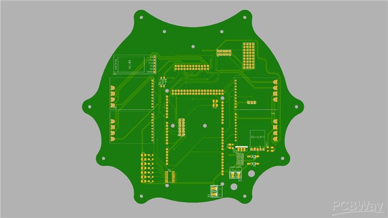
Main Board
The main board of our robot. It’s purpose is to connect every module to the MCU ( ATMega2560 on board of Arduino Mega board).

It contains the slots for the following modules:
Arduino Mega (for computing capabilities)
BNO055
4x VHN5019 motor drivers (3 for the mobility gearmotors and 1 for the dribbler)
12V LiPo battery
3.3V and 5V voltage regulators for electronics
TFT Display and encoder for built-in GUI
Integrated kicker electronics
Custom Line sensing modules ports
SPI and I2C bus extension slots ( for the Pixy camera, and for future modules )
The interaction between the modules and the MCU is mostly interrupt-based in order to maintain real time handling of events.
Line sensing module (LSM)
The platform uses 3 of these modules, each coupled with a gearmotor. This final design comes after a lot of experiments done in the years by the Phoenix team. Our final solution is driven by the use of a special chip: ADS1015, a 10-bit resolution ADC, provided with I2C interface. Each module has its own address (every I2C bus can handle no more than 4 LSM, due to ADS1015 address selection limit)

Each LSM handles 3 pairs of leds and photodiodes, used to sense changes in ground color around the gearmotor, from green to white or, green to black. The MCU will provide to interpret output values from the module, estimating the line position around the robot.
Luziato’s platform
Main Board
The board has the same purpose as valepercy’s one, but taking one more step in lightness. Most of the modules previously listed as integrated onto the board, have ben removed.

A standardized set of ports have been inserted, in order to attach future modules with more ease (like the display module, or sonar distance module).
Line Sensor
The line sensor boards results much simpler to insert inside the robot, as it’s made of a single pair of led and photodiode, directly attached to the MCU ADC pins

This approach results much more easier and robust, at the expense of response frequency, since all the conversions have to be made by the MCU. However as said before, this solution results in a much easier and direct way to read changes in ground colors.
Kicker Power Module (KPM)
The KPM is an external module, which handles the higher currents needed by the kicker. It is been decoupled from the main board for fault tolerance reasons. It contains the circuit needed to safely control the flow of current going through the kicker.

The core of the module, is the logic level controlled MOSFET transistor: P16NF06
We would gladly accept any support you could give us with the manufacturing of these 4 robots !
Thanks from Phoenix team

- Comments(0)
- Likes(3)


