


SUBHAJIT BARMAN
INDIA • + Follow
Description
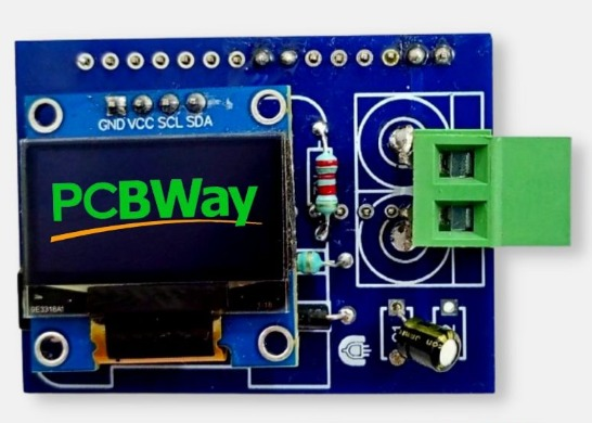
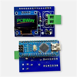
Arduino Inductance Meter DIY
Make a pocket-sized inductance meter using Arduino, capable of precisely measuring 41uH to 30mH inductance values. Additionally, it can easily measure lower and higher inductance values than the specified range. Read continue (schematic, how it works, connection guides, etc.) - Arduino Inductance Meter.
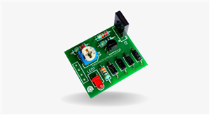
Parts Placement Instructions for PCB:
- U1: Arduino Nano
- U2: IC LM339
- OLED1: 0.96 128x64 Oled Display
- R1: 2k2 1/4W Resistor
- R2: 150 1/4W Resistor
- D1: 1N4001 Diode
- C1: 2u2 25V Capacitor
- L1: ? (Testing Inductance...)
Feb 24,2024
1,325 views
Arduino Inductance Meter DIY
Make a pocket-sized inductance meter using Arduino, capable of precisely measuring 41uH to 30mH inductance values.
1325
1
0
Published: Feb 24,2024
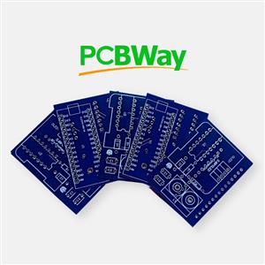
Standard PCB
Download Gerber file 19
BOM(Bill of materials)
PCBWay Donate 10% cost To Author
File Last Updated: 2024/02/26 (GMT+8)
File update record
2024-02-2609:37:54
Parts List (BOM) is updated.
Only PCB
PCB+Assembly
*PCBWay community is a sharing platform. We are not responsible for any design issues and parameter issues (board thickness, surface finish, etc.) you choose.


Under the
Attribution-NonCommercial (CC BY-NC)
License.


- Comments(0)
- Likes(1)
Upload photo
You can only upload 5 files in total. Each file cannot exceed 2MB. Supports JPG, JPEG, GIF, PNG, BMP
0 / 10000
More by SUBHAJIT BARMAN
-
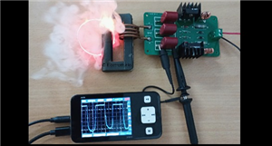 Powerful ZVS Driver
A Zero Voltage Switching (ZVS) circuit is a popular device among electronics hobbyists for creating ...
Powerful ZVS Driver
A Zero Voltage Switching (ZVS) circuit is a popular device among electronics hobbyists for creating ...
-
 KY-022 Infrared Receiver Module
The KY-022 module is an infrared receiver that reacts to 38kHz IR light. It can be used to receive c...
KY-022 Infrared Receiver Module
The KY-022 module is an infrared receiver that reacts to 38kHz IR light. It can be used to receive c...
-
 Simple Peak Detector Circuit Board
A peak detector is an electronic circuit designed to identify and hold the highest value (peak) of a...
Simple Peak Detector Circuit Board
A peak detector is an electronic circuit designed to identify and hold the highest value (peak) of a...
-
 Arduino Inductance Meter DIY
Make a pocket-sized inductance meter using Arduino, capable of precisely measuring 41uH to 30mH indu...
Arduino Inductance Meter DIY
Make a pocket-sized inductance meter using Arduino, capable of precisely measuring 41uH to 30mH indu...
-
 300W Pure Sine Wave Inverter with EGS002 SPWM Driver Board
This full sinusoidal inverter with EGS002 SPWM driver board can convert the 12V DC to 220V AC with 5...
300W Pure Sine Wave Inverter with EGS002 SPWM Driver Board
This full sinusoidal inverter with EGS002 SPWM driver board can convert the 12V DC to 220V AC with 5...
-
 Lithium BMS Module For Overcharging Protection
This single Battery Management System (BMS) module can monitor the 1S cell at a maximum current of 1...
Lithium BMS Module For Overcharging Protection
This single Battery Management System (BMS) module can monitor the 1S cell at a maximum current of 1...
You may also like
-
-
-
-
Tester for Touch Screen Digitizer without using microcontroller
330 2 2 -
Audio reactive glow LED wristband/bracelet with NFC / RFID-Tags
310 0 1 -
-
-


