|
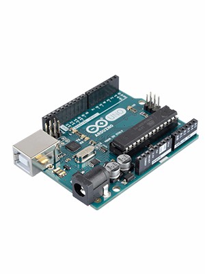
ARDUINO UNO REV3 |
x 1 | |

|
ATTINY85-20PUMicrochip Technology
|
x 1 |

|
Soldering iron |
|

|
Soldering Iron Wire Welding Lead Roll |
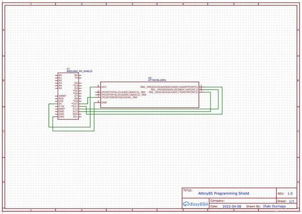
Attiny85 Programmer Shield for Arduino UNO
An Arduino UNO shield for Attiny85 Programming.
Programming ATtiny boards can be a tiring labor, so make it faster and easier with this shield!
Step 1: Add Support for the ATtiny85 to the Arduino URL Board Manager
By default the Arduino IDE does not support the ATtiny85 so it's required to add support for the Attiny85 to the Arduino Board Manager:
From the Arduino IDE Go to Arduino->Preferences then scroll down to Additional Board Managers URLs
Copy & paste the following (if you already have a board manager URL just add a comma before pasting)
Press "OK" at the bottom then restart the Arduino IDE
Step 2: Install the ATtiny Board Package From the Arduino IDE go to Tools--> Board-->Boards Manager
A new tab will open and at the top of the tab type: attiny
Select Install on the Attiny by David. A Mellis
Restart the Arduino IDE
The ATtiny85 board should now be added ! Go to Tools--> Board-->Attiny85
Step 3: Set the Arduino Uno Into ISP Mode
Since what we want is to be able to program the ATtiny85 from the Arduino IDE which requires to burn the bootloader to the ATtiny85 we will need to "prep" the Arduino fist by uploading the ISP sketch to it.
In the Arduino IDE select File-->Examples--> 11. Arduino ISP-->ArduinoISP
the ISP sketch should open and upload it to your Arduino Uno
Step 4: How a Microcontrollers Pins Are Labeled
Before the connections are made there is a very important fact to know how pins on microcrontrollers/ICs are labeled.
Pin numbers used to program a chip on the Arduino IDE are based on how the chip manufacturer has internally named/aranged the pins . The manufacturer of the ATtiny85 is ATMEL (the AT in ATtiny85-actually stands for ATMEL);It's common for chips to have the first two initials of the company who makes them.
Pins are gathered into groups called "ports" these ports are labeled A,B,C etc. Each port has a number of pins which are labeled 0,1,2,3 etc and stick out on different parts of the chip which is why a microcontroller's physical pin often time will be different than the pin number used when programming the chip.
An example:
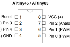
PB0 (in the above datasheet) just means pin 0 is located on Port B of the Chip.
If pin 0 was located on Port A the name would look something like PA0 (Port A pin 0)
To add to the complexity pins can have more than one fuction and be labeled multiple names.
Wrapping it all together! :
Writing a program to light an LED on pin 0 on the ATtiny85 might be confusing at first because just by looking at the chip , there is no pin 0! However, by checking the datasheet of the ATtiny85 from ATMEL-snippet shown above-pin 0 is internally located on the chip's port B (and is actually the chip's physical pin 5 )!
Step 6: Making the ATtiny85 Arduino Compatible
By default any fresh microcontroller chip bought will not be able to be programmed with the Arduino IDE out of the box. This is why it's required to burn the Arduino bootloader onto the chip to make sure the chip will accept any programs uploaded via the Arduino IDE.
Quick checklist before pressing "burn bootloader"
Go to Tools -> Board scroll to the bottom select ATtiny25/45/85
Under Tools -> Processor--> 8 MHz (internal)
Under Tools-->Programmer-->Arduino as ISP
Check that all wiring, capacitor, and board selections are correct
Finally select Burn Bootloader
leave the wires connected they will be used in the next step
A message will appear saying "Done Burning Bootloader"
Step 7: Uploading the Blink Sketch
Test that the ATtiny85 can now receive sketches from the Arduino IDE by uploading the blink example
Go to File-->Example-->01.Basics-->blink
Edit the sketch by replacing pin 13 with 0
Make sure to still have the ATtiny85 board settings from the previous step selected
Make sure all wiring is the same as the previous step
Upload the sketch
Wire an LED by connecting the anode to pin 0 (physical pin 5 ) and the cathode to a 1K resistor connected to ground (physical pin 4)
While a resistor is not needed since the battery provides 3v (not enough to blow up an LED) it is recommended to lower the brightness of the LED.
Hope it helps on future projects!
Attiny85 Programmer Shield for Arduino UNO
*PCBWay community is a sharing platform. We are not responsible for any design issues and parameter issues (board thickness, surface finish, etc.) you choose.
- Comments(0)
- Likes(2)
-
 virginia perez barriga
Jan 08,2023
-
 Inaki Iturriaga
Oct 03,2022
- 0 USER VOTES
- YOUR VOTE 0.00 0.00
- 1
- 2
- 3
- 4
- 5
- 6
- 7
- 8
- 9
- 10
- 1
- 2
- 3
- 4
- 5
- 6
- 7
- 8
- 9
- 10
- 1
- 2
- 3
- 4
- 5
- 6
- 7
- 8
- 9
- 10
- 1
- 2
- 3
- 4
- 5
- 6
- 7
- 8
- 9
- 10
 More by Inaki Iturriaga
-
 Battery-Powered ESP32-CAM Continuous Video Recorder
OverviewThis project transforms an ESP32-CAM module into a standalone, battery-powered video recordi...
-
 GPS Mobile Beacon
Building a GPS Emergency Beacon: A DIY TutorialWelcome to our latest DIY project: creating a GPS Eme...
-
 Wireless RFID Card Copier.
Wireless RFID Card CopierIn today's digital world, security and accessibility are of paramount impor...
-
 Piezo Alert System.
Within the fast-evolving sphere of security tools and home automation, creativity often paves the wa...
-
 Wifi Weather Station - Sensors board
WiFi Weather Station - Sensor unitIn our digital era, many electronics projects integrate diverse se...
-
 Building a GPS Speedometer with RP2040-Zero
Build a Feature-Packed GPS Speedometer with an RP2040This project guide will walk you through buildi...
-
 RC Receiver
Build Your Own RC ReceiverHarnessing advanced electronics and precise control systems, the RC Receiv...
-
 Universal RC Controller
Build Your Own Universal RC RemoteHarnessing the power of custom PCBs and wireless communication, th...
-
 Continuous GPS Tracker
This compact and efficient tracker provides real-time location updates, making it ideal for surveill...
-
 Air Quality Monitor
Welcome to our DIY tutorial on assembling an Air Quality Monitoring Device. This project is perfect ...
-
 Automatic Watch Winder
In the realm of luxury timepieces and watch aficionados, an automatic watch is...
Automatic Watch Winder
Automatic Watch WinderIn the realm of luxury timepieces and watch aficionados, an automatic watch is...
-
 Handheld GPS
Within the swiftly advancing realm of portable technology and travel essentials, innovation often sh...
-
 Dual Motor Controller for Model Robotics
In the thrilling world of robotics and DIY engineering, innovation continues to soar to new heights....
-
 Altitude Indicator with Beeper for Rocketry
Altitude Indicator for Model RocketryIn our ever-advancing technological landscape, countless projec...
-
 Wifi Weather Station - Display unit
WiFi Weather Station - Display UnitIn this technologically advanced age, countless electronics proje...
-
 Positon Breakout Board
Position Sensors Breakout Board In today's era of advanced technology, many electronics projects req...
-
 Ambient Sensors Breakout Board
In today's world, electronics projects often require the integration of multiple sensors to collect ...
-
 Infrared Launch Controller
IntroductionHave you ever wanted to remotely launch a rocket, drone or other device using infrared t...
-
-
AEL-2011 Power Supply Module
513 0 2 -
AEL-2011 50W Power Amplifier
473 0 2 -
-
-
Custom Mechanical Keyboard
688 0 0 -
Tester for Touch Screen Digitizer without using microcontroller
321 2 2 -
Audio reactive glow LED wristband/bracelet with NFC / RFID-Tags
306 0 1 -
-
-


