


|
|
DC Gear Motor |
x 2 | |
|
|
M3 Bolts and Nuts |
x 1 | |
|
|
Arduino Board |
x 1 | |
|
|
L293D Motor Driver Shield |
x 1 | |
|
|
3S 7.4V Li-Ion Battery |
x 1 | |
|
|
Required 3D Parts |
x 1 |

|
arduino IDEArduino
|
|

|
3D Printer (generic) |
|

|
Soldering iron (generic) |
|

|
Solder Wire, Lead Free |
3D Printed Theo Jansen Style Octopod Robot (Arduino Based)
Hi everyone! In this project, I will show you an amazing eight-legged robot in the Octopod style! It is made entirely from 3D-printed parts and moves with a cool mechanism inspired by the Jansen Mechanism. Two simple DC motors power the legs, allowing them to move in a smooth and balanced way. A simple Infrared sensor circuit and controller were used to control the robot. I will start the project by assembling the 3D pieces step by step, just like a puzzle, so let's get started!
Step 1: 3D Parts and Hardware

The project consists of a total of 79 pieces of 3D parts, but don't be intimidated, the main parts are 55 pieces in total and their thickness is approximately 3 millimeters. The remaining 24 pieces are clip-washer 3D parts. I did the printing with Bamboo Lab A1 in standard, i.e. medium quality, the printing time for all parts took about 6 hours.
I avoided using a single color when printing the parts, my aim was to ensure that you can easily distinguish the joints and main parts during assembly. At first I printed in one color and completed the assembly and then I realized that it would be difficult for viewers or readers to distinguish the parts, so I hope that the parts with different colors will make it easier for you during assembly.
During the assembly of the 3D parts, 2 pieces of simple DC Gear Motor were used as hardware, usually sold as a set with wheels and is very popular among Makers. Technically, it is usually operated in the range of 5 to 6 Volts and has a speed of about 200 to 255 RPM.
In addition, a total of 18 bolts and 4 nuts were used during assembly. Dimensions are below:
- 8 pieces M3 12MM bolts (for base, top and sides)
- 4 pieces M3 25MM Bolts (for DC Motors)
- 4 pieces M3 Nut (for DC Motors)
- 2 pieces M3 20MM bolts (for axe-drive)
- 2 pieces M3 16MM bolts (for axe-drive)
- 2 pieces M2 12MM Bolt (for axe-mtr)
Step 2: Assembly of the Chassis

In this section we will first assemble the chassis. First of all, fix the Right and Left Side models to the Base model using M3 12MM bolts. But, without fully tightening the bolts of any side, place the Upper model and complete the assembly by tightening all the bolts.
Step 3: Mounting of DC Gear Motors

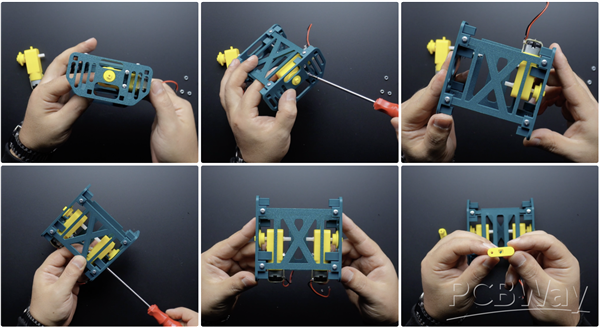

In this section, we will mount the DC Gear Motors, first of all, insert 4 pieces of M3 25MM bolts into the bolt inputs on the Right and Left Sides. Then place the models named axe-mtr.stl on the DC motor shafts. Thread the DC motors onto the M3 25MM bolts on the chassis and tighten the bolts by installing M3 nuts. Insert the axle part with the long shaft in the model file containing the parts named axe-drive.stl into the motors (axe-mtr model) and fix it by tightening with M2 12MM screws. Now we can move on to the leg assembly.
Step 4: Joining the Legs

This section requires a total of 8 Leg (leg.stl) parts, 4 on each side. To join the first legs (i.e. the ones in purple in the image, the first ones to be attached to the motor), joint models called inks_1.stl are used. These have a shorter shaft. Insert the joining parts into the leg parts as shown in the image and use the clips clip-washer.stl to fasten them.

Next, joint models called inks_2.stl are used to join the second legs (i.e. the parts in dark green in the image, the parts that will overlap the purple leg). These have a longer shaft. Insert the joining parts into the leg parts as shown in the picture and use clip-washer.stl to secure the clips.
Step 5: Placing and Assembling the Legs on the Chassis

In fact, it might be a bit complicated to explain this section in writing, so I have added markers to some of the shared images to make it easier (of course you can also refer to the video for this section).
On both sides of the chassis, there are two square mounting holes for the axe-main.stl parts that we previously attached to the legs. Insert the axe-main.stl parts into these holes as shown in the image and insert the legs into the chassis. In the meantime, you should insert the part with a circle-shaped hole from the inks_1.stl parts in the purple legs to the motor shaft. The part of the dark green leg with the circle-shaped hole should remain free in this position, it will be inserted at a later step. Then insert the second leg into the chassis in the same way.

After the purple colored parts (in inks_1.stl) are attached to the motor shaft, insert the circle-shaped shaft separator part in axe-drive.stl into the motor shaft with the purple colored parts on the bottom. Place the short shaft axle part from the model file containing the parts named axe-drive.stl on the previously fixed motor axle and fix it with M3 20MM bolts.

Now, place the leg parts with the circle-shaped hole in the dark green legs on the axle with the short shaft, and then fix them with M3 16MM bolts by placing the circular washer with the center hole in the axe-drive.stl model file.
Finally, attach the clip-washer-bg.stl parts to the ends of the axe-main.stl parts on the top and bottom of the chassis. That's all, the 3D part assembly of the robot is now complete!
Step 6: Circuit

Now that the 3D parts of the robot are complete, we can take a look at the circuit. You can actually create the circuit with an Arduino board and a motor driver shield, but in this project I will use a two-in-one circuit board of my own design. I used this circuit board in a previous project and it was very much appreciated by my followers.
So I made some updates and shared the final version on the PCBWay project page. This board design is simple but very efficient, it combines a motor driver and a microcontroller, making it easy for projects involving motors. When designing the PCB prototype, I took care to choose components that are easy to find and solderable.


The board basically consists of three main components, an ATmega328P, an L293D motor driver, I used a CH341 chip for easy programming via USB. Only, the CH341 USB chip might seem a bit difficult to solder. But using a simple soldering iron, apply a small amount of solder to the pads on the PCB where the chip will be mounted, then align the chip legs correctly and complete the soldering with the soldering iron. If you are not experienced with soldering, you can use PCBWay's assembly board service and they will send you a ready-to-use board.


Among the images, I have shared an image of the Bill of Materials and a Designator image with the positions of the components.
The circuit uses an infrared remote control and receiver for wireless control. The IR remote control and receiver is a very functional and simple product, suitable for robotics and hobby DIY applications. It is usually sold as a 2-in-1 set.
Usually Kit includes:
- Remote controller (approx. 21 buttons)
- 38 kHz 1838B IR Receiver Module
- Jumper cables

A 3S 7.4-volt Li-Ion battery was also chosen to power the circuit. Just connect the motors and the infrared sensor to the circuit as follows, then insert the circuit board and battery into the robot.
- Motor A1 = Digital 2
- Motor A2 = Digital 4
- Motor B1 = Digital 11
- Motor B2 = Digital 10
- IR Pin = Digital 12

Now that the robot mechanism and circuit are complete, it's time to program it!
Step 7: Source Code

Before moving on to the main source code, we need to find out which commands, i.e. HEX values, the buttons on the remote control send. Download the infrared remote control command finder code I shared in the attachment and open it with Arduino IDE.

In this and the main code we used an IR library, first we need to install the IR library, and make sure you have installed version 2.6.0 of the library. The library GitHub link is here: https://github.com/Arduino-IRremote/Arduino-IRremote , but as you can see in the image, you can easily install the library by searching for IRremote using the Arduino IDE library tool.


Then define the pin to which the infrared receiver is connected and upload the code to the board. Then open the serial monitor and press the buttons you will use on the remote control, you will see the commands for the buttons on the screen. Remember to make a note of the commands because they will be used in the next step.

If you have received the commands for your controller, we can move on to the main code (Motor_Control_IR_Code). Download the code and open it with Arduino IDE, and make the following changes:
- Update the pins to which the motors are connected
- Update the pin to which the IR receiver sensor is connected
- Update HEX values received from the remote control
The loop() function handles commands received from an infrared (IR) remote control and controls the motors accordingly.
- IR signal detection: Commands are read and processed from the IR sensor.
- Avoiding repeated commands: If the same command is received consecutively, it is ignored, and only new commands are processed.
- Command matching and motor control: The received command is matched against predefined HEX values, and the corresponding motor function is executed:
- FWRD: Motors move forward
- BKWD: Motors move backward
- LEFT: Motors turn left
- RGHT: Motors turn right
- STOP: Motors stop
- IR receiver reset: The IR receiver is reset to be ready for the next signal.
- Error handling and timing: A small delay is applied when the sensor is busy, ensuring stable operation.
If everything is ready, upload the code to the board, if you are using the printed circuit board I designed, you need to select the board as Arduino UNO.
Now it's time to control the robot! Thanks for reading, I hope it has been a helpful resource for your projects. Have a great making!
3D Printed Theo Jansen Style Octopod Robot (Arduino Based)
*PCBWay community is a sharing platform. We are not responsible for any design issues and parameter issues (board thickness, surface finish, etc.) you choose.


- Comments(4)
- Likes(20)
- 1 USER VOTES
- YOUR VOTE 0.00 0.00
-
10design
-
10usability
-
10creativity
-
10content
More by MERT KILIC
-
 3D Printed Theo Jansen Style Octopod Robot (Arduino Based)
Hi everyone! In this project, I will show you an amazing eight-legged robot in the Octopod style! It...
3D Printed Theo Jansen Style Octopod Robot (Arduino Based)
Hi everyone! In this project, I will show you an amazing eight-legged robot in the Octopod style! It...
-
 Creative Modular LED Lighting with Magnetic Pogo Pins & Wi-Fi Control
Hi everyone! Welcome to my latest project: a modular, plug-in LED lighting system that is as fun as ...
Creative Modular LED Lighting with Magnetic Pogo Pins & Wi-Fi Control
Hi everyone! Welcome to my latest project: a modular, plug-in LED lighting system that is as fun as ...
-
 Build a simple 3D printed CNC plotter machine
Hi friends, do you remember this Mini CNC Plotter machine that uses hobby stepper motors and a few 3...
Build a simple 3D printed CNC plotter machine
Hi friends, do you remember this Mini CNC Plotter machine that uses hobby stepper motors and a few 3...
-
 Circuit Activity Board - Educational Electronics
Circuit Activity Board – A Hands-On Project to Learn Basic ElectronicsIn this project, we're going t...
Circuit Activity Board - Educational Electronics
Circuit Activity Board – A Hands-On Project to Learn Basic ElectronicsIn this project, we're going t...
-
 Build a Simple 3D Wall Lighting
Hi friends, this project shows how to make and control 3D hexagonal LED lighting panels. The project...
Build a Simple 3D Wall Lighting
Hi friends, this project shows how to make and control 3D hexagonal LED lighting panels. The project...
-
 Robot Sumo Board
Robot-sumo, or pepe-sumo, is a sport in which two robots attempt to push each other out of a circle ...
Robot Sumo Board
Robot-sumo, or pepe-sumo, is a sport in which two robots attempt to push each other out of a circle ...
-
 ESP32 Mecanum Wheels Robot and Bluetooth Gamepad Controller
In this project we will see how to make an ESP32 Mecanum Wheels Robot which is capable of moving in ...
ESP32 Mecanum Wheels Robot and Bluetooth Gamepad Controller
In this project we will see how to make an ESP32 Mecanum Wheels Robot which is capable of moving in ...
-
 DIY Motorized WiFi Roller Blind - ESP8266 & Blynk
In this project we will see how to control a roller blind via a smartphone application. The reason w...
DIY Motorized WiFi Roller Blind - ESP8266 & Blynk
In this project we will see how to control a roller blind via a smartphone application. The reason w...
-
 Pet Feeder Controlled Via WiFi - ESP8266
How It Works?As you can see, a 3D design was used for the pet feeder. ESP8266-based Wemos D1 Mini bo...
Pet Feeder Controlled Via WiFi - ESP8266
How It Works?As you can see, a 3D design was used for the pet feeder. ESP8266-based Wemos D1 Mini bo...
-
 ESP8266 Two Wheel Robot (NodeMCU and Stepper Motor)
Generally, robot cars are built on a chassis with 2 DC motor wheels and a bovine wheel. While surfin...
ESP8266 Two Wheel Robot (NodeMCU and Stepper Motor)
Generally, robot cars are built on a chassis with 2 DC motor wheels and a bovine wheel. While surfin...
-
 3D Printed Rotating Table Board with Arduino Nano and 28BYJ-48 Stepper Motor
This project shows how to make a 3D printed Rotating Table using Arduino and a hobby stepper motor. ...
3D Printed Rotating Table Board with Arduino Nano and 28BYJ-48 Stepper Motor
This project shows how to make a 3D printed Rotating Table using Arduino and a hobby stepper motor. ...
-
 Hand Gesture Controller for Robotic
The hand gesture controller makes it possible to control applicat...
Hand Gesture Controller for Robotic
Hand Gesture Controller for RoboticThe hand gesture controller makes it possible to control applicat...
-
 How To Make DIY Remote Control Hoverboat at Home
In this video, I showed you how to make your own hoverboat from materials available at home and chea...
How To Make DIY Remote Control Hoverboat at Home
In this video, I showed you how to make your own hoverboat from materials available at home and chea...
-
 How to Make DIY Arduino Gesture Control Robot at Home
Parts Required for Receiver (Tank):1) Robot Tank Chassis - https://bit.ly/3j8y2Q52) Arduino Nano V3 ...
How to Make DIY Arduino Gesture Control Robot at Home
Parts Required for Receiver (Tank):1) Robot Tank Chassis - https://bit.ly/3j8y2Q52) Arduino Nano V3 ...
-
 DIY Circuit Activty Board with Paperclips | MAKER | STEM
You can be creative and design your own circuit and add different sensors (other LEDs...). The idea ...
DIY Circuit Activty Board with Paperclips | MAKER | STEM
You can be creative and design your own circuit and add different sensors (other LEDs...). The idea ...
-
 ATtiny85 Wearable Activity Tracking Watch
How to make the wearable activity tracking watch? This is a wearable gadget designed to vibrate when...
ATtiny85 Wearable Activity Tracking Watch
How to make the wearable activity tracking watch? This is a wearable gadget designed to vibrate when...
-
 How to Build a Motorized 3D Scanning Turntable for Your Phone
In this project, I’ll show you how to make a simple motorized turntable for 3D scanning. It has thre...
How to Build a Motorized 3D Scanning Turntable for Your Phone
In this project, I’ll show you how to make a simple motorized turntable for 3D scanning. It has thre...
-
 DIY Motorized 3D Scanning Turntable
In this project, I’ll show you how to make a simple motorized turntable for 3D scanning. It has thre...
DIY Motorized 3D Scanning Turntable
In this project, I’ll show you how to make a simple motorized turntable for 3D scanning. It has thre...
-
-
mammoth-3D SLM Voron Toolhead – Manual Drill & Tap Edition
211 0 0 -
-
-
-
Tester for Touch Screen Digitizer without using microcontroller
440 2 2 -
Audio reactive glow LED wristband/bracelet with NFC / RFID-Tags
392 0 1 -
-


