
|
EagleAutodesk
|
Car battery maintenance charger
Maintenance charger
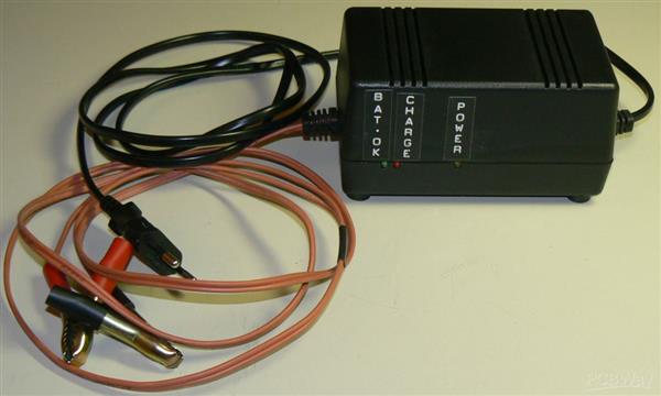
On this page you find all the information needed to build a maintenance charger for lead-acid batteries. It has protection against short circuit and reverse connection. The charger has automatic temperature compensation, unlike most of the popular CTEK chargers.
 Background
In 1998 summer issue of Elektor Electronics, a maintenance charger for lead-acid batteries was published. I built 4 pcs of these chargers, and some years later, 3 pcs more. I have used them on our tractors, combine harvester and summer car batteries during winter. Before that, each year at least one tractor needed a new battery. Now there can be several years that none of them needs to be renewed. I just connect the chargers in autumn, and the batteries and machines are in cold shed for the winter. When the machines are needed for sowing in spring, I disconnect the charger and they are ready for use. They don't need any attention during winter. After over 20 years of service, all the chargers are still working. Two of them have been repaired however, since they got damaged when connected with incorrect polarity.
Recently, I needed one more charger. The easiest solution nowadays would be to buy a commercial charger, e.g. CTEK. Back in 1998, commercial maintenance chargers were not available. However, most of the CTEK models still don't have automatic temperature compensation. And, can I be sure that it would work for 20+ years? Well, maybe the real reason of not buying a commercial charger was that I wanted another project :)
Updated charger design
At first I was thinking of re-drawing the PCB to get Gerber files. My old charger boards were hand drawing using Decon Dalo 33 pen, and then etched at home. The original Elektor design is rather big work to build, because the enclosure doesn't have PCB mounting posts. Also, it doesn't have fool-proof protection. I decided to make partial re-design of the circuit to make it easier to build and also fix some problems of the original design. Changes compared to original:
- Designed to fit into readily available enclosure
- PCB transformer on same board. Eliminates one possible bad connection (DC jack)
- Relay replaced with transistor to eliminate contact wear problems (haven't had any during the 20+ years though!)
- Current limit protects against short circuit
- Reverse battery connection protection with buzzer warning
- If mains cable gets disconnected during use, charger doesn't drain the battery (except the 0.1 mA battery OK LED current)
The PCB is designed with Cadsoft Eagle. Below is Eagle 3D rendition of the board.
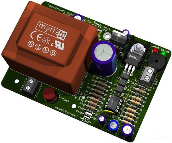
Downloads for the design files, Gerber files and documentation are below. You can order bare boards from PCBWay, see line on top right pane on this page. Here is TME shared project which contains all the components for the project.
maintenance_charger_v11.zip Eagle .sch and .brd
maintenance_charger_v11.pdf Circuit diagram, assembly drawing and BOM
maintenance_charger_v11_gerber.zip Gerber files
Circuit operation
One method of maintenance charging is float charging. This means that the charger produces constant voltage, e.g. 13.8 V, which is continuously applied to the battery. This means that the battery is constantly full. At least in theory, this could cause some unwanted boiling in battery.
This charger stops charging when the battery voltage reaches 13.8 V. The charging starts when voltage drops to 12.6 V. This ensures that battery is always full enough to prevent from freezing and sulphation. These voltage switchpoints are temperature compensated. In 0ºC, the switchpoints are and 14.3 and 13.1 V.
Build and adjustment
The parts of TME shared project are shown below (M3 screw and nut for TO220 heatsink fixing are not included in in shared project)
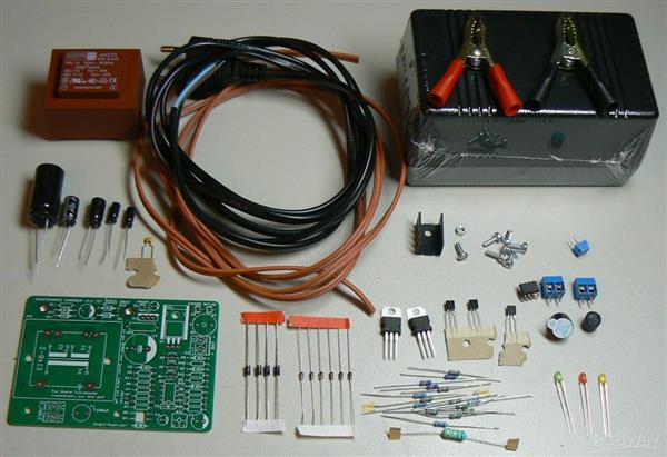
Assembly of the unit is straightforward. The heatsink for transistor doesn't need to be isolated. Leave LED legs long enough, so the LEDs can be bent to side seam of enclosure.
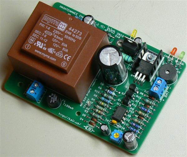
The Myrra transformer can be fixed to PCB with two 3 x 8 mm plastic screws. The same screws are required to fix the PCB to enclosure. The enclosure only includes the screws needed to close the enclosure. Circuit diagram lists alternative PCB transformers from different manufacturers, but only the Myrra brand has the screw holes. The other types are held in place only by solder joints.
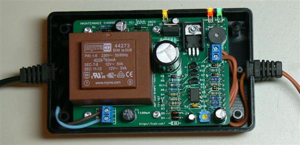
You can route the cables around the posts for added strain relief. The brown cable is LAPP 0065202, 2x0,75mm2 with silicone insulation. It stays flexible in cold, but the insulation is easy to tear at sharp edges. It is so soft that you can strip it with your nails. The PVC mains cable becomes very stiff when cold.
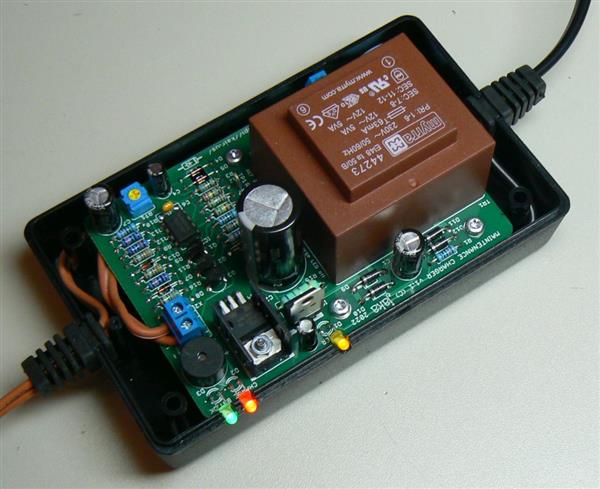
Before use, the voltage threshold needs to be adjusted. Measure voltage from TP1, and adjust with RT1. Set the voltage to 2.1 V when charge LED does not light. If ambient temperature is other than +20ºC, compensate this reading -4 mV/ºC. For example, if the adjustment is done at 0ºC, adjust TP1 voltage to 2.18 V. The adjustment is easier if you connect the charger to a full battery, or if you connect big enough capacitor to output terminals. Otherwise, the charge LED is off only very briefly. The adjustment procedure is described on schematic diagram and on bottom of the board as well. Another tip is to keep the charger powered for some time, with enclosure closed, before adjustment. This takes the self heating of charger into account.
Usage
Using the charger is simple. Connect the charger to battery. Ensure that the green 'BATTERY OK' LED lights. Then connect mains cable. Ensure that yellow 'POWER' LED lights. All set! The red 'CHARGE' LED indicates that the battery is being charged.
If you are visiting the location where battery/vehicle is stored, it is worth checking that both yellow and green LEDs are constantly lit. It indicates that all is OK. If the yellow LED is off, the charger is not getting power. If the green LED is flashing, it indicates that connection to battery is not good.
Car battery maintenance charger
*PCBWay community is a sharing platform. We are not responsible for any design issues and parameter issues (board thickness, surface finish, etc.) you choose.
- Comments(0)
- Likes(4)
-
 Jeffery Thompson
May 29,2024
-
 MUSTAFA CAKICIOGLU
Jan 09,2024
-
 Олег Липовий
May 20,2023
-
 Engineer
Mar 24,2023
- 1 USER VOTES
- YOUR VOTE 0.00 0.00
- 1
- 2
- 3
- 4
- 5
- 6
- 7
- 8
- 9
- 10
- 1
- 2
- 3
- 4
- 5
- 6
- 7
- 8
- 9
- 10
- 1
- 2
- 3
- 4
- 5
- 6
- 7
- 8
- 9
- 10
- 1
- 2
- 3
- 4
- 5
- 6
- 7
- 8
- 9
- 10
-
10design
-
10usability
-
10creativity
-
10content
 More by jaka
-
 PICkit2- programmer
The PICkit2- programmer, PK2M for short, is yet another clone of the Microchip PICkit2 PIC programme...
-
 Car battery maintenance charger
Maintenance chargerOn this page you find all the information needed to build a maintenance charger f...
-
 12V timer relay with delay on release
Delay relayA simple, solid state delayed off 'relay' for 12V and 24V systems. You could use it to co...
-
 Toyota Hilux Vigo interior light LED upgrade
Toyota Hilux Vigo ceiling light LED modification I replaced my Hilux interior light incandescent bul...
-
 LED board for IL arcade buttons (outside version)
IL arcade buttons LED modificationI am a fan of the IL (Industrias Lorenzo, S.A.) arcade buttons and...
-
 LED board for IL arcade buttons (inside version)
IL arcade buttons LED modification I am a fan of the IL (Industrias Lorenzo, S.A.) arcade buttons an...
-
 Hardsid ISA clone
This is a reincarnation of the Hardsid clone which I made almost 20 years ago. The ...
Hardsid ISA clone
Hardsid ISA cloneThis is a reincarnation of the Hardsid clone which I made almost 20 years ago. The ...
-
 Microchip ICD to PICkit adapter
This simple adapter allows to use Microchip ICD programmers with targ...
Microchip ICD to PICkit adapter
Microchip ICD to PICkit adapterThis simple adapter allows to use Microchip ICD programmers with targ...
-
 BJT water detector
DIY water detector / leak alarmHere is simple water detector you can build yourself. It can be used ...
-
 J-ACE Arcade Controls Encoder
Jaka Arcade Controls Encoder The J-ACE is a DIY USB keyboard encoder. It allows you to make e.g. an ...
-
 DIY Weller WMRT compatible handle
Here are desoldering tweezers that you can build yourself. They use...
DIY Weller WMRT compatible handle
DIY Weller WMRT compatible handleHere are desoldering tweezers that you can build yourself. They use...
-
 Accurate digital wall clock with GPS and remote control
Kello version 4This is fourth version and maybe final version of my seven segment digital wall clock...
-
 Weller WMRP and WMRT compatible soldering station
This driver can be used with Weller tips which have integrated heater element and temperature sensor...
-
 Temperature difference thermostat v2.1
Temperature difference thermostat which can be used to control heating. When the inside temperature ...
-
 Speed test
A DIY replica of electronic speed test game, manufactured by Coinline in Finland. A similar game is ...
-
 JAKADAPTER - Dual Atari joystick USB adapter
This adapter allows to connect two Atari style joysticks, paddles, or Sega Megadrive / Genesis gamep...
-
-
mammoth-3D SLM Voron Toolhead – Manual Drill & Tap Edition
252 0 0 -
-
AEL-2011 Power Supply Module
780 0 2 -
AEL-2011 50W Power Amplifier
647 0 2 -
-
-
Custom Mechanical Keyboard
841 0 0 -
Tester for Touch Screen Digitizer without using microcontroller
463 2 2 -
Audio reactive glow LED wristband/bracelet with NFC / RFID-Tags
408 0 1 -
-


