
|
arduino IDEArduino
|
|

|
KiCADKicad
|
ESP32 Smart Watch
This project contains two PCBs, this is the Main PCB, and there is a Second PCB, please click https://www.pcbway.com/project/shareproject/Second_PCB_for_ESP32_Smart_Watch_239e6110.html
In this we are going to use what we have learned to create our own smartwatch from scratch, using a combination of hardware and software components. Throughout this part of the project, you will be guided through the process of assembling the hardware components, setting up the software, and configuring the settings and features of your smartwatch. By the end of this project, you will have a fully functional smartwatch that you can wear and use on a daily basis.
You can read the full article and explanation about the project on the Circuit Digest website
Features of ESP32 Smartwatch
· 1.69” IPS TFT Display with a resolution of 280x240 pixels
· Single button control
· Deep Sleep power-saving Mode
· Auto wakeup with accelerometer
· Auto brightness adjust using an ambient light sensor
· Digital compass for navigation
· Heart Rate Monitor
· Multiple cool-looking watch faces
· Intuitive menu system
· Inbuilt game for entertainment
· Micro SD card
· Vibration motor
· Battery charging capability with deep discharge protection
Components Required to Build the ESP32 Smart Watch

All the parts you will require to build the smartwatch are listed below. The exact value of each component can be found in the schematics or the BOM.
· TTGO Micro-32 V2.0 x1
· IPS6404L PSRAM IC x1
· 1.69” TFT display with ST7789V controller x1
· MAX809T 3V Power supervisor Reset controller x1
· CP2102 USB UART controller x1
· MCP7383 1S battery charger x1
· DW01 Battery protection IC x1
· FS8205A MOSFET x1
· NCP167AMX330TBG 3.3V LDO x1
· XC6202P182MR 1.8V LDO x1
· MPU6050 Accelerometer IC x1
· HMC5883L Magnetometer Sensor IC x1
· LSM303DLHC Accelerometer Magnetometer IC (Optional, replaces MPU6050 and HMC5883L) x1
· MAX30102 Hear Rate sensor x1
· BH1750FVI Ambient light sensor x1
· S8050 SOT-23 NPN transistor x3
· Micro SD Slot x1
· 10mm Vibration Motor x1
· 1N5819 SMD diode x2
· LED5D5 TVS ESD protection Diodes(optional) x3
· Micro USB Port x1
· 0.5mm pitch 10 pin FPC connector x2
· SMD Resistors
· SMD Capacitors
· PCB
· Other tools and miscellaneous
ESP32 Smart Watch Complete Circuit Diagram
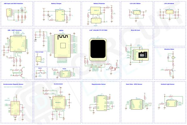
The complete circuit diagram for the ESP32 Smart Watch is shown below. It can also be downloaded in PDF format from the link given at the end.
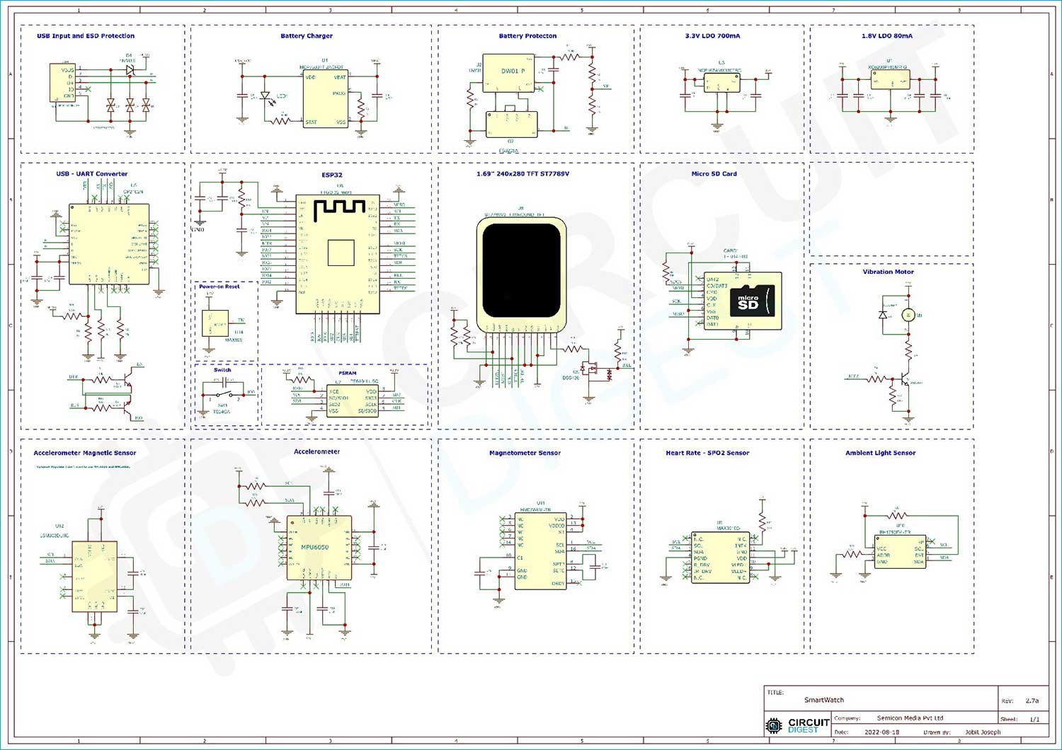
Let’s discuss the Schematics section by section for better understanding. The micro-USB port is used for both charging as well as programming purposes. The power and data connections from the micro-USB port are connected to TVS ESD protection diodes. These diodes will protect the entire circuit from any ESD spikes on the USB input. The 5V from the USB port is then connected to the input of the MCP7383 1S Li-ion battery charger. The output from the charging IC is then fed to the protection circuit built around the DW01 IC and the FS8205 MOSFET. This protection circuit combination will protect the battery from over-current discharges and deep discharges.

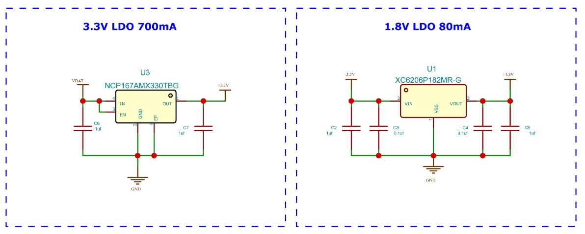
The power then passes through two LDOs. The main voltage regulator used in the circuit is the NCP167AMX330TBG from ON Semi. It can provide a maximum current of 700ma. The main advantage of using this chip is the size. The NCP167AMX comes in a 1mmx1mm 4-XDFN package. Which saves a lot of space. The second Low voltage regulator in the circuit is an XC620P182MR-G 1.8V LDO. This LDO is used for the MAX30102 Heart Rate sensor chip.
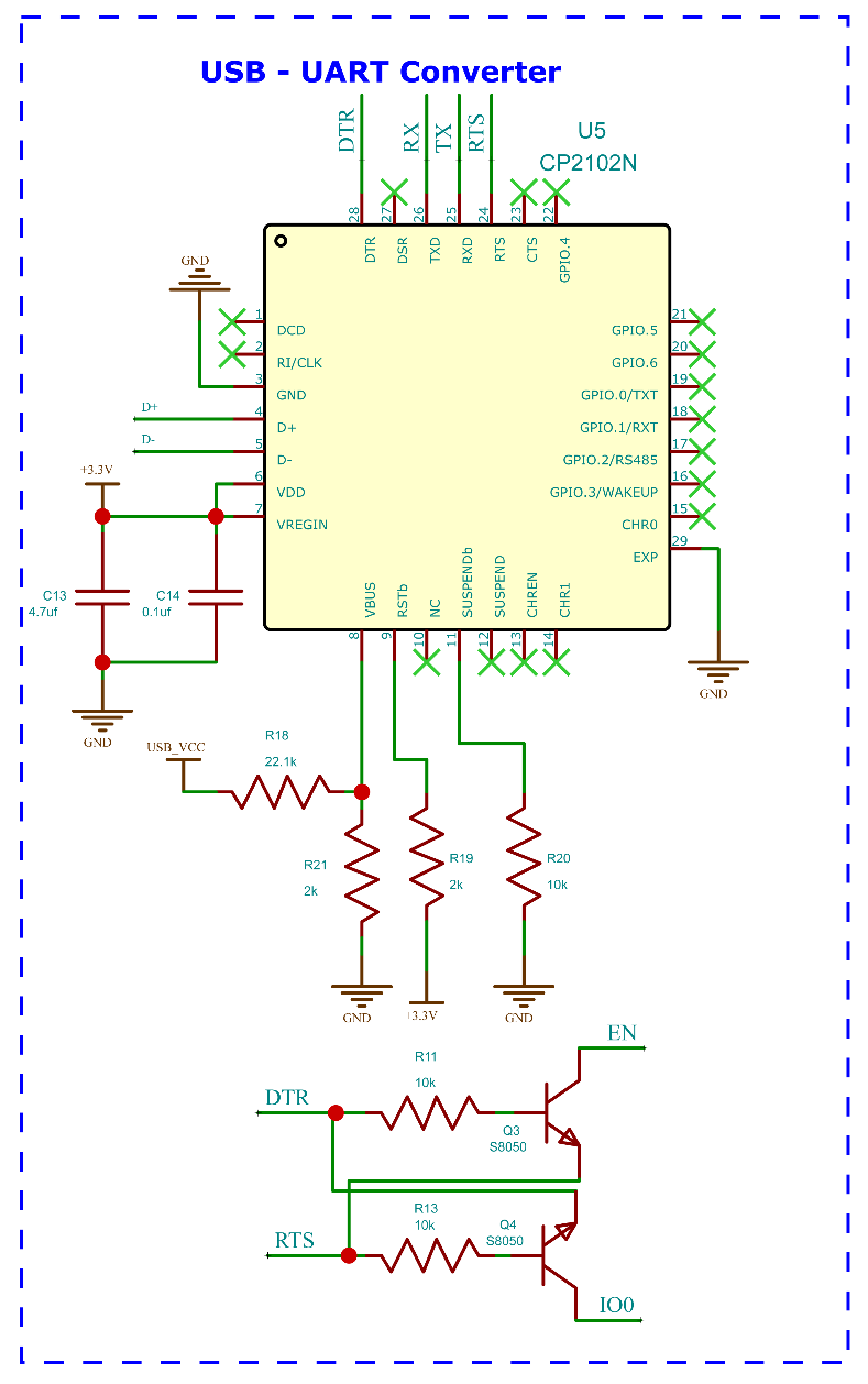
The next section is the USB UART controller. This section is designed around the CP2102N from Silicon Labs. It supports a maximum speed of 12Mbps. A minimal number of external components along with the small QFN-24 package makes it a better choice among other controller chips in the same category. The auto-reset circuit for the ESP32 is built around two S8050 NPN transistors. The transistors are connected to the DTR and RTS pins of CP2102 and EN and RST pins of ESP32. This enables us to program the ESP32 without the need for a reset button.
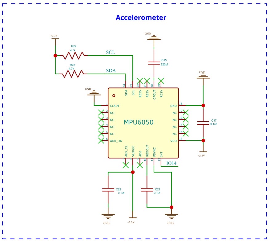
The MPU6050 accelerometer chip is used to detect motion. This feature enables us to wake the smartwatch with a simple hand movement. The interrupt pin of the MPU6050 is connected to the GPIO14 of the ESP32 controller. When a movement exceeding the set threshold is detected the MPU6050 will send an interrupt signal to the ESP32 to wake it from deep sleep.
The next sensor is the HMC5883 magnetometer sensor. This sensor is used to implement the digital compass functionality. While using this sensor make sure there is no magnetic interference or any metals nearby, which may produce wrong readings.
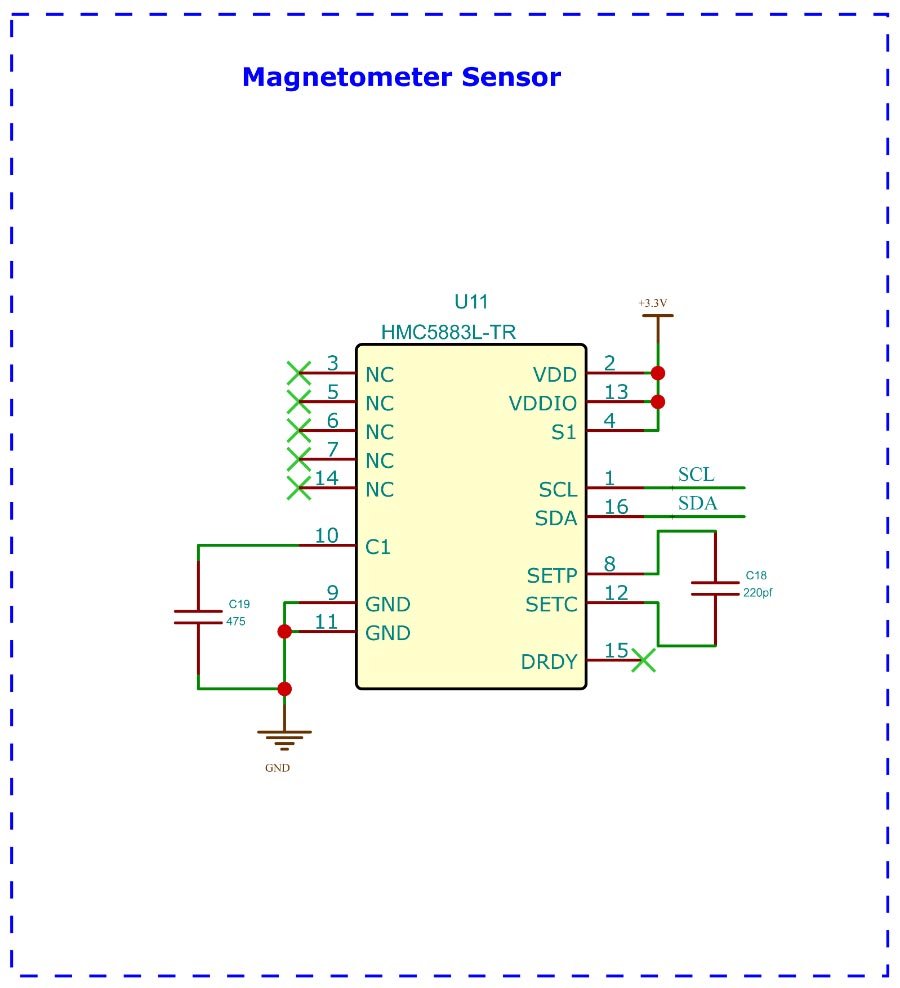
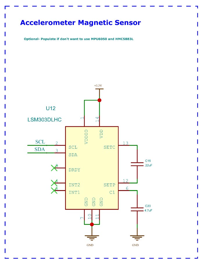
In the PCB we have also reserved a space for the LSM303 chip, which combines both accelerometer and magnetometer sensors. This sensor is included in case, we don’t want to use the MPU6050 and HMC5883L. It’s a reserved component. You don’t have to populate it if you are using the MPU6050-HMC5883 combination.
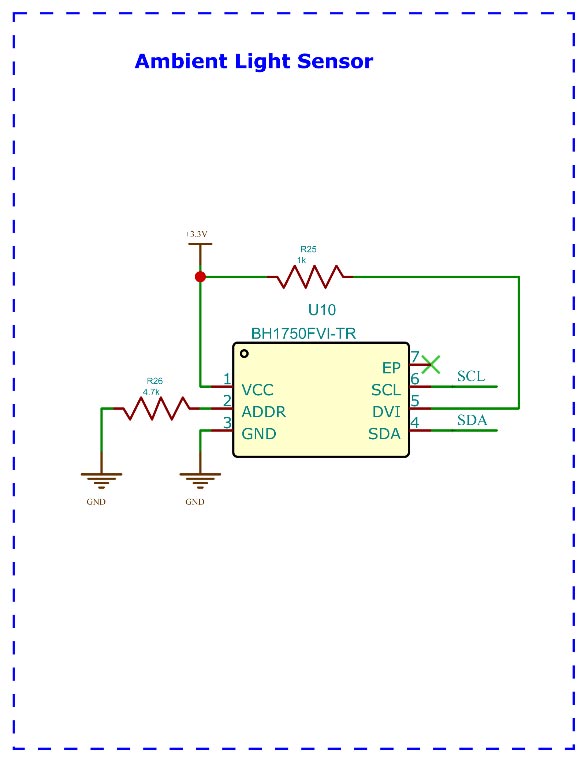
Next, we have the BH1750 ambient light sensor. This sensor is used in order to achieve the auto-brightness control. This sensor is placed on the front side below the TFT display. A small hole is provided in the enclosure to measure the ambient light. If auto-brightness is enabled the MCU will read the ambient light data from BH1750, and the display backlight will be adjusted accordingly.
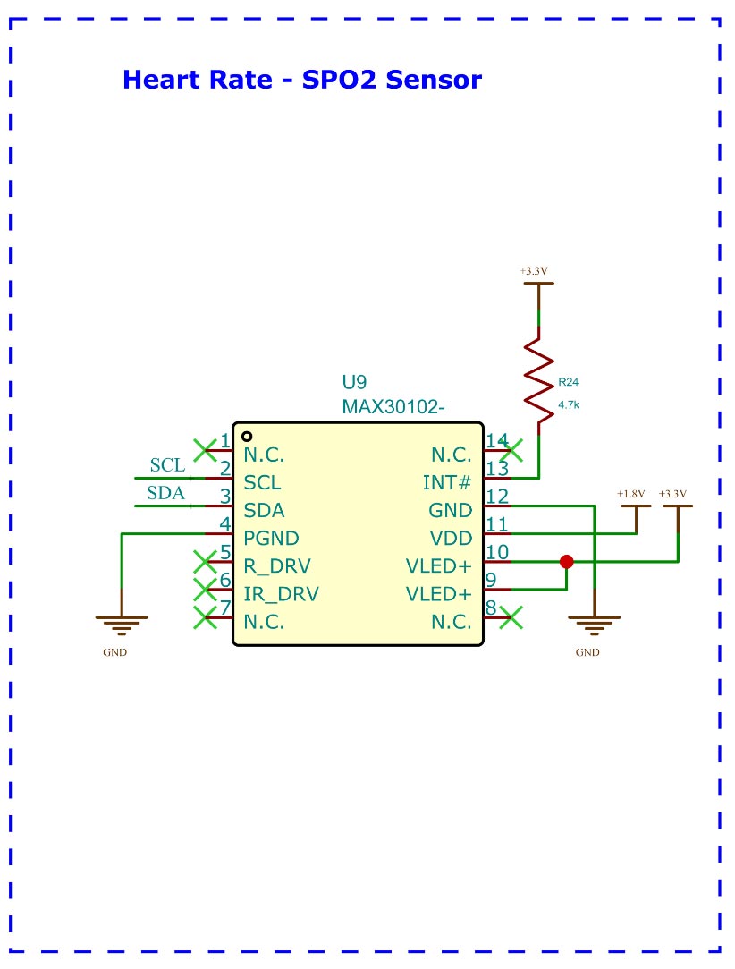
For measuring the heart rate, we have used the MAX30102 from Maxim Integrated. This sensor works on a 1.8v supply voltage and is capable of detecting heart rate using light sensors. The code is tuned in a way that the chip won't falsely trigger when the watch is placed on a surface other than the wrist or finger.
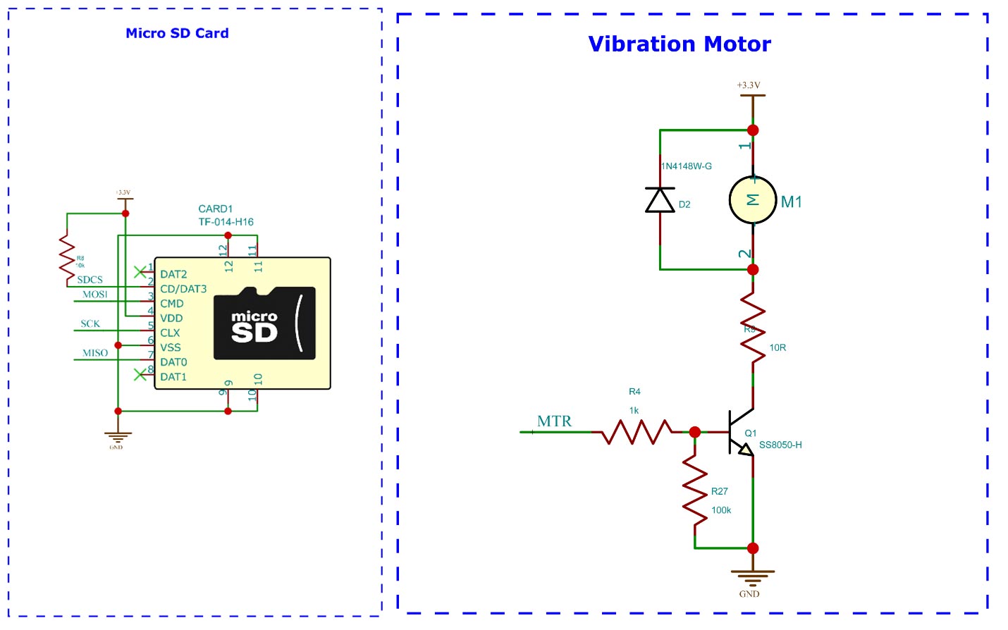
We have also included a micro-SD slot and a vibration motor in the PCB for future developments. At this moment these are not configured or utilised in the code. The micro-SD shares the same SPI bus as the TFT display. It can be used to store data such as firmware files, monitoring logs or even watch face data or images. The vibration motor is controlled using a S8050 NPN transistor. A freewheeling diode is also connected across the motor to protect the circuit from any voltage spikes.
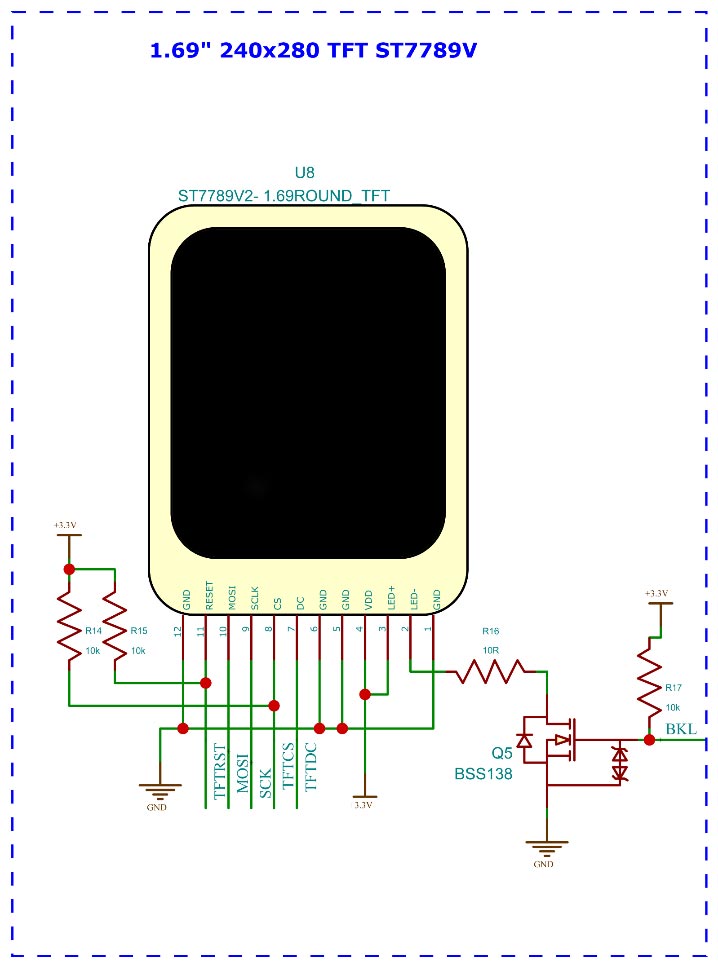
For the display, we have used the 1.69” display with rounded corners. This IPS display gives a very nice display contrast and colour saturation. This display uses the ST7789 display driver. The ST7789 can support SPI bus frequency up to 100MHz. This will enable us to drive the display much faster providing better FPS. The backlight is controlled using a N-Channel MOSFET. PWM is used to control the brightness.
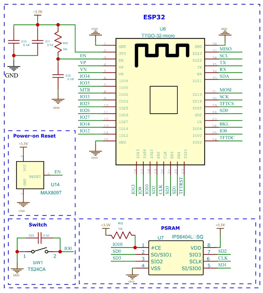
The heart of this project is the TTGO Micro-32 V2.0 module from LILYGO. It is based on the ESP32-PICO D4 SIP with integrated ESP32 SoC, crystal oscillator, filter capacitors, RF matching links, and 4MB flash, in a single 7mm × 7mm QFN package. We have also used an IPS6404L PSRAM along with the module. The MAX809T MPU supervisor chip is used to make sure the ESP32-PICO-D4 is power cycled during the cold boot. This chip will keep the ESP32 under reset condition until the threshold voltage is reached. Once the threshold voltage is reached the MAX809T (3V Reset threshold) will reset the ESP32 and will clamp the enable pin to VCC.
PCB for ESP32 Smartwatch
For the PCB we have chosen the two-board design. The top board contains the MCU along with the display, UART controller, power circuitry, light sensor and the MPU6050 chip. The bottom board contains HMC5883, LSM303, MAX30102, a microSD slot and the vibration motor. The two boards are connected using a 10-pin FPC cable with a pitch of 0.5mm.
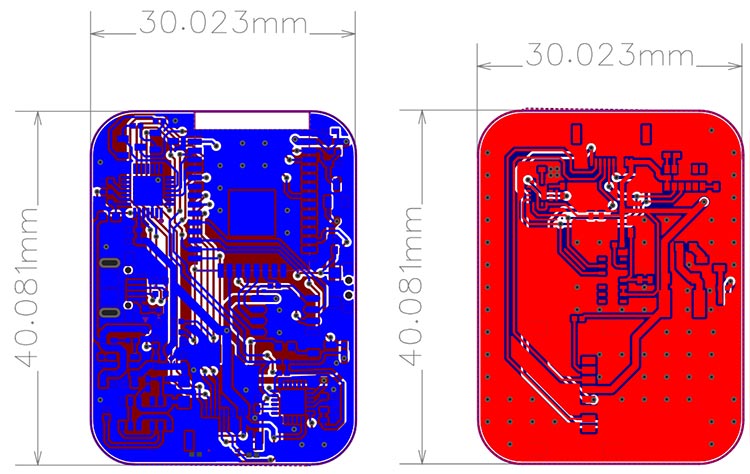
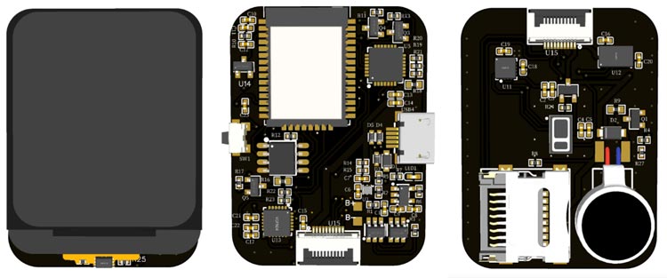
Here is the 3D view of both the boards
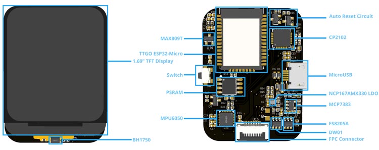
Here are all the components on the main board labeled.
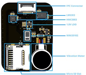
And here is the daughterboard with components marked.
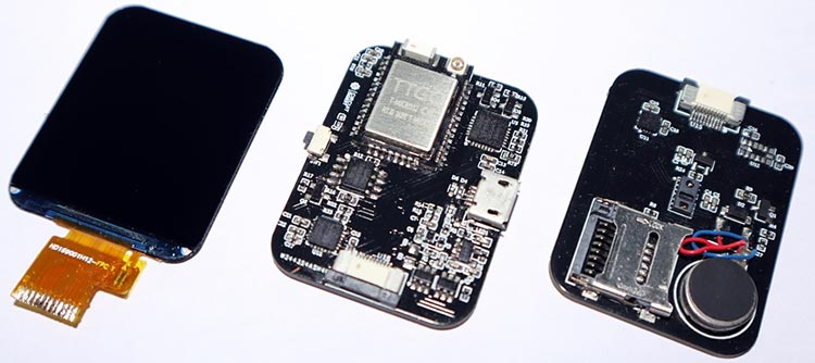
Here are the fully assembled board along with a TFT display.
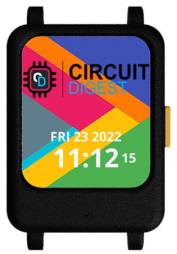
Here is the image of a fully assembled smartwatch.
3D Printed Parts
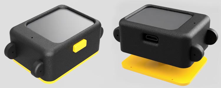
We have designed a cool-looking 3D-printed enclosure for the smartwatch. The files for all the 3D printed parts can be downloaded from the GitHub link provided at the end of the article along with the Arduino sketch and bitmap file. It is recommended to print the parts with higher infill for better quality and sturdiness. Learn more about 3D printing and how to get started with it by following the link.
ESP32 Smart Watch GUI Navigation
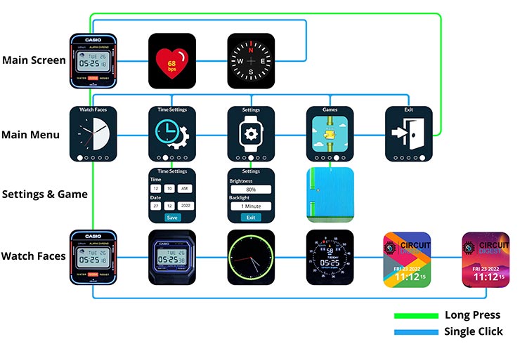
The whole GUI is designed in a way that we can navigate through every option using a single button. We can use short and long presses to navigate through them. You can find the whole GUI flow in the below image. The blue line indicates single/short clicks, while the green line indicates long presses. In the Time Settings and Settings menu, you can navigate through each option or field using short clocks. Select the option and use the long press to change the value.
Arduino Code for the SmartWatch
You can read the full article and explanation about the code on Circuit Digest website
ESP32 Smart Watch
*PCBWay community is a sharing platform. We are not responsible for any design issues and parameter issues (board thickness, surface finish, etc.) you choose.
- Comments(3)
- Likes(4)
-
 Engineer
Jun 09,2025
-
 Electronic Adam
Apr 13,2025
-
 Engineer
Dec 25,2024
-
 Engineer
Mar 13,2024
- 0 USER VOTES
- YOUR VOTE 0.00 0.00
- 1
- 2
- 3
- 4
- 5
- 6
- 7
- 8
- 9
- 10
- 1
- 2
- 3
- 4
- 5
- 6
- 7
- 8
- 9
- 10
- 1
- 2
- 3
- 4
- 5
- 6
- 7
- 8
- 9
- 10
- 1
- 2
- 3
- 4
- 5
- 6
- 7
- 8
- 9
- 10
 More by Jobit Joseph
-
 How to build a Wearable Air Quality Monitor Pendant using STM32 & SGP40 Sensor
This DIY Wearable Air Quality Monitor Pendant is a compact, battery-powered device designed to conti...
-
 Smart Digital Ludo Game Board with Multicolour PCB
Ludo, a beloved childhood game, holds a special place in our hearts with its simple and engaging gam...
-
 Electronic Dice with BLE Connectivity
Many of us fondly remember the joy of playing board games like Snakes and Ladders or Ludo during our...
-
 3D printed Enclosure Backplate for Riden RD60xx power supplies
3D printed Enclosure for Riden RD60xx power supplies such as RD6006, RD6012, RD6018, RD6024 and RD60...
-
 3D printed Enclosure for Riden RD60xx power supplies
 such as RD6006, RD6012, RD6018, RD6024 and RD60...
3D printed Enclosure for Riden RD60xx power supplies
3D printed Enclosure for Riden RD60xx power supplies such as RD6006, RD6012, RD6018, RD6024 and RD60...
-
 Suzuki Ignis Universal Armrest No Screw Adapter
I own a 2024 Suzuki Ignis. When I searched for an armrest for my car I couldn't find any domesticall...
-
 Wireless Potentiostat for Electrochemical Analysis
This wireless potentiostat is based on the ADuCM355 SoC from Analog Devices, tailored for portable e...
-
 160 Channel Configurable DAC Controller
The DAC controller board features 160 individually controllable 16-bit DAC output. It can output vol...
-
 Build Your Own ESP32 AI Voice Assistant with MCP Integration
Project OverviewThe ESP32 AI Voice Assistant with MCP Integration is an advanced voice-controlled sm...
-
 Build Your Own Precision Digital Micro-Current Meter with STM32
In many electronic projects — especially those involving battery-powered devices or low-power sensor...
-
 DIY Meshtastic Using ESP32 : Build Your Own Private Off-Grid Network
Project OverviewThis project delivers a complete, custom-designed PCB solution for building Meshtast...
-
 Second PCB for ESP32 Smart Watch
This project contains two PCBs, this is the Second PCB,and there is a Main PCB, please click https:/...
-
 1S battery Charger with Battery level indicator and power path
1S Battery Charger with Battery level indicator and 5V out and standby mode.
-
 Smart Universal Remote with Learning Function and Google Assistant Support
In our day-to-day life, we use various gadgets such as televisions, set-top boxes, air conditioners,...
-
 High-Resolution POV Display using ESP32
In this guide, we'll learn how to create a cool POV display using an ESP32 module. It's all about us...
-
 Low Cost Drone using ESP32
Drones have rapidly evolved from niche hobbies to versatile tools with a wide range of applications,...
-
 DIY Thermal Camera
Ditch X-ray vision, thermal cameras are the real industrial superheroes! They don't just see light, ...
-
 ESP32 Smart Watch
This project contains two PCBs, this is the Main PCB, and there is a Second PCB, please click https:...
-
-
mammoth-3D SLM Voron Toolhead – Manual Drill & Tap Edition
88 0 0 -
-
AEL-2011 Power Supply Module
602 0 2 -
AEL-2011 50W Power Amplifier
542 0 2 -
-
-
Custom Mechanical Keyboard
746 0 0 -
Tester for Touch Screen Digitizer without using microcontroller
371 2 2 -
Audio reactive glow LED wristband/bracelet with NFC / RFID-Tags
346 0 1 -
-


