|
KiCADKicad
|
|

|
arduino IDEArduino
|
DIY Thermal Camera
Ditch X-ray vision, thermal cameras are the real industrial superheroes! They don't just see light, they see heat, making them masters of uncovering hidden energy drains, pinpointing overheating gadgets, and even aiding soldiers in the dark. They're invaluable in industries like tech repair, where they sniff out shorted circuits like electronic bloodhounds. The only catch? Their price tag can be a bit frosty. But hey, technology is always evolving, and soon, thermal vision might be just as common as your phone camera! So remember, that seemingly ordinary camera might just be packing some extraordinary heat-sensing powers.
A few months back I created such a thermal camera with easy-to-find components. Here I'm sharing that project with you hoping some of you may find this helpful. So, in this project, we are going to find some solution for that by making a DIY thermal imager using much cheaper available components. The cheaper thermal imaging sensors we have considered are the AMG8833 from Panasonic, MLX90640 and MLX90641 from Melexis. Even though the AMG8833 is the cheapest of them all it only has a resolution of 8x8, while MLX90640 offers a resolution of 32x24 and MLX90641 offers a resolution of 16x12. Since the MLX90640 offers the best resolution in the price range we choose it for our DIY thermal camera.
Features
- Image sensor resolution: 32x24.
- Sensor field of view (FoV): 55°x35°
- Temperature measurement range: -40 to 300°C
- -40 to 85°C operational temperature range.
- Adjustable refresh rate – 4Hz – 32Hz.
- 10 different colour palettes.
- 5 different interpolation modes.
- Easy to use GUI.
- 2.4” TFT display with 320x240 resolution.
- Save thermal image to SD card.
- Built-in battery and charging circuit.
- Open source
Schematic Design
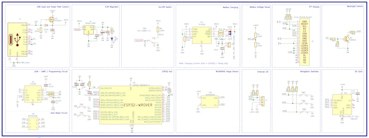
The complete circuit diagram for the DIY Thermal Camera is shown above. It can also be downloaded in PDF format. We have used KiCad to design the schematics and PCB for this project, you can find the complete files on the GitHub repo. To understand everything easily I have divided the schematics into different sections and marked everything accordingly.

Here we have the power section. It consists of a USB C connector for power input and programming, a power path controller built around AO3041 MOSFET, a 3.3V regulator and a battery charging circuit built around the TP4056 charge controller. A voltage divider is used to measure the battery voltage. The power switch is connected to the enable pin of the 3.3V LDO.

Next, we have the main circuitry, which includes the ESP32 SoC, USB to UART controller and the MLX90640 image sensor. The programming circuit uses a CH340K chip for USB communication. A dual N-channel MOSFET is used for auto-reset circuit. The MLX90640 is interfaced to the ESP32 using I2C. An additional I2C port is also provided in case if needed for anything else.
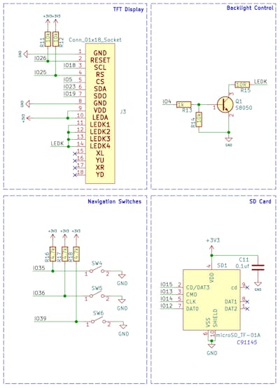
Last we have the display, micro SD card and button inputs. The display uses hardware HSPI bus for interfacing with ESP32. The micro SD interface uses the VSPI pins on the ESP32 module. Detecting key presses we are using simple pushbuttons connected to the GPIOs and ground.
PCB Design
We have used KiCad for designing the PCB. We have used a simple two-layer layout for our PCB because they are cheap and easy to get manufactured. The PCB has a dimension of 80mm x 50mm. Here are the top and bottom layers of the PCB.

And here is the 3D view of the PCB.

Finally, here is the fully assembled PCB.
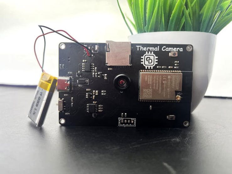
Assembled PCB
DIY Thermal Camera Overview
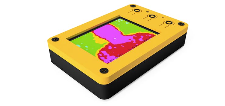
Here is the overall overview of a fully assembled DIY Thermal Camera.
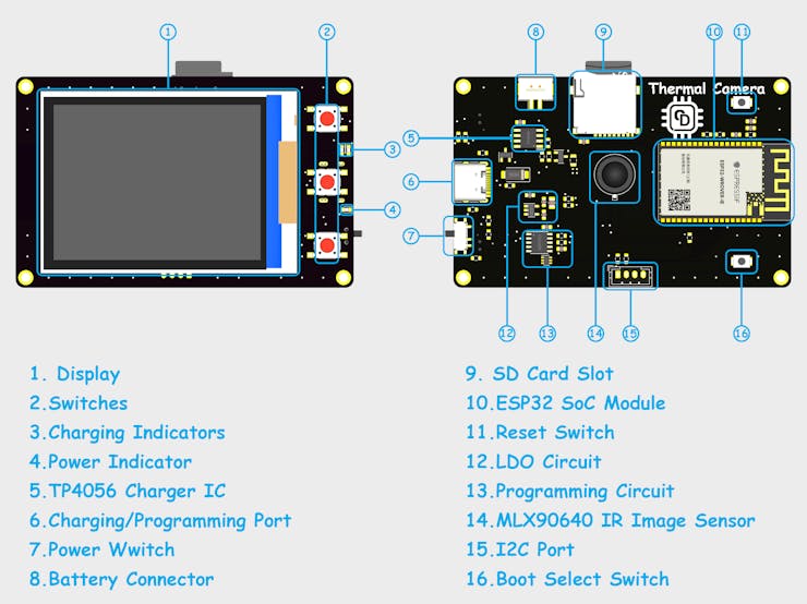
PCB Parts Overview
3D Printed Parts
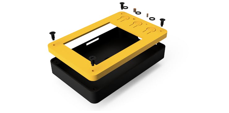
We have designed a cool-looking 3D-printed enclosure for the DIY thermal camera. The files for all the 3D printed parts can be downloaded from the GitHub/Thingiverse link provided below.
3D Render
Enclosure 3D render
How to Use the Thermal Camera
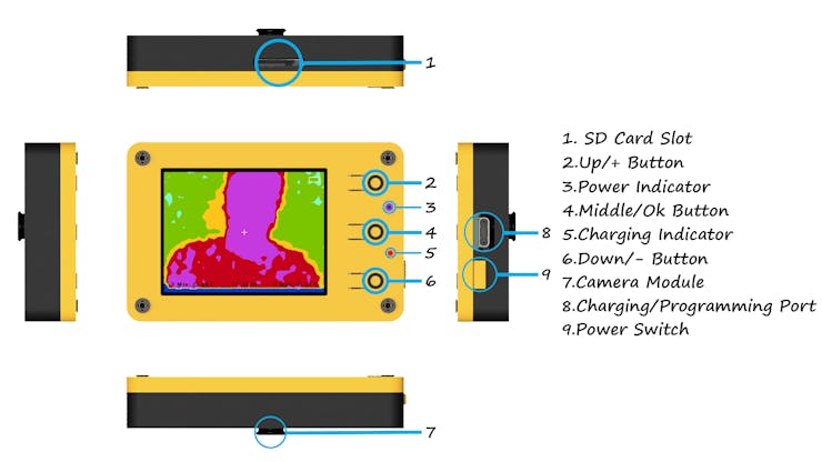
Overview
The button usage is the following.
Up/+ Button:
Default: Change/cycle through interpolation mode.
In Settings: Change the selected value.
Middle/Ok Button:
Default: Short press: Save images to SD card.Long Press: Enter the settings menu.
In Settings: Short press: Change the selection in the menu.Long Press: Exit the settings menu.
Down/- Button:
Default: Change colour pallet.
In Settings: Change the selected value.
Here is the main screen interface. On the main screen, you can see the thermal image itself along with the minimum, maximum and middle point temperatures and battery icon.
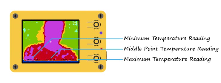
Main Screen
The image below shows the Settings screen of the DIY thermal camera. The settings have 7 options. The selected option will show in green text while others will be shown in white text. You can change the selection by short-pressing the middle button. The value of the selected option can be adjusted using the Up/+ or Down/- button.
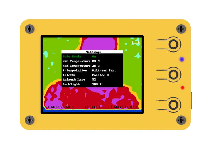
Settings Screen
Here are the settings options and the corresponding values available.
- Auto Scale:
- Auto-scale on : Colour will display according to the maximum and minimum temperature readings from the sensor.
- Auto scale off : Colour will display according to the maximum and minimum temperature set manually.
- Min Temperature: Minimum temperature for colour palette calculation when the auto scale is off.
- Max Temperature: Maximum temperature for colour palette calculation when the auto scale is off.
- Interpolation: Interpolation method. It refers to the interpolation algorithm used to upscale the low-resolution image from the sensor(32x24) to the high-resolution image(320x240) displayed on the screen. Depending on the interpolation method the quality of the image as well as the image processing time will change. The available methods are the following.
- Nearest Neighbor
- Average
- Bilinear
- Bilinear Fast
- Triangle
- Palette: The colour palette refers to the different display modes. There are 10 different palettes available to select.
- Refresh Rate: Refresh rate of the image sensor. The MLX90640 supports refresh rates from 0.5Hz to 64Hz. But while testing the most usable refresh rates were 4Hz, 8Hz, 16Hz and 32 Hz. So, we have only included these refresh rates.
- Backlight: Backlight brightness. You can set it from 10% to 100%.
Source
The project was originally published on Circuit Digest. You can find more details on the DIY Thermal Camera Project Page.
Show Case
Here are some of the images taken using our thermal camera.


DIY Thermal Camera
*PCBWay community is a sharing platform. We are not responsible for any design issues and parameter issues (board thickness, surface finish, etc.) you choose.
- Comments(0)
- Likes(17)
-
 Sergio Oliveira
Jun 24,2025
-
 Engineer
May 03,2025
-
 Engineer
Apr 20,2025
-
 Electronic Adam
Apr 13,2025
-
 Aaron Shaw
Apr 06,2025
-
 Anthony Pedotto
Feb 22,2025
-
 Prasanna K
Nov 05,2024
-
 Engineer
Sep 29,2024
-
 vicente orellana
Sep 22,2024
-
 Kenji
Aug 18,2024
-
 Engineer
Jun 22,2024
-
 Engineer
May 05,2024
-
 Engineer
Apr 05,2024
-
 Engineer
Mar 13,2024
-
 Engineer
Mar 07,2024
-
 Jobit Joseph
Feb 26,2024
-
 (DIY) C64iSTANBUL
Feb 21,2024
- 0 USER VOTES
- YOUR VOTE 0.00 0.00
- 1
- 2
- 3
- 4
- 5
- 6
- 7
- 8
- 9
- 10
- 1
- 2
- 3
- 4
- 5
- 6
- 7
- 8
- 9
- 10
- 1
- 2
- 3
- 4
- 5
- 6
- 7
- 8
- 9
- 10
- 1
- 2
- 3
- 4
- 5
- 6
- 7
- 8
- 9
- 10
 More by Jobit Joseph
-
 How to build a Wearable Air Quality Monitor Pendant using STM32 & SGP40 Sensor
This DIY Wearable Air Quality Monitor Pendant is a compact, battery-powered device designed to conti...
-
 Smart Digital Ludo Game Board with Multicolour PCB
Ludo, a beloved childhood game, holds a special place in our hearts with its simple and engaging gam...
-
 Electronic Dice with BLE Connectivity
Many of us fondly remember the joy of playing board games like Snakes and Ladders or Ludo during our...
-
 3D printed Enclosure Backplate for Riden RD60xx power supplies
3D printed Enclosure for Riden RD60xx power supplies such as RD6006, RD6012, RD6018, RD6024 and RD60...
-
 3D printed Enclosure for Riden RD60xx power supplies
 such as RD6006, RD6012, RD6018, RD6024 and RD60...
3D printed Enclosure for Riden RD60xx power supplies
3D printed Enclosure for Riden RD60xx power supplies such as RD6006, RD6012, RD6018, RD6024 and RD60...
-
 Suzuki Ignis Universal Armrest No Screw Adapter
I own a 2024 Suzuki Ignis. When I searched for an armrest for my car I couldn't find any domesticall...
-
 Wireless Potentiostat for Electrochemical Analysis
This wireless potentiostat is based on the ADuCM355 SoC from Analog Devices, tailored for portable e...
-
 160 Channel Configurable DAC Controller
The DAC controller board features 160 individually controllable 16-bit DAC output. It can output vol...
-
 Build Your Own ESP32 AI Voice Assistant with MCP Integration
Project OverviewThe ESP32 AI Voice Assistant with MCP Integration is an advanced voice-controlled sm...
-
 Build Your Own Precision Digital Micro-Current Meter with STM32
In many electronic projects — especially those involving battery-powered devices or low-power sensor...
-
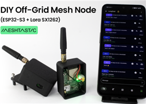 DIY Meshtastic Using ESP32 : Build Your Own Private Off-Grid Network
Project OverviewThis project delivers a complete, custom-designed PCB solution for building Meshtast...
-
 Second PCB for ESP32 Smart Watch
This project contains two PCBs, this is the Second PCB,and there is a Main PCB, please click https:/...
-
 1S battery Charger with Battery level indicator and power path
1S Battery Charger with Battery level indicator and 5V out and standby mode.
-
 Smart Universal Remote with Learning Function and Google Assistant Support
In our day-to-day life, we use various gadgets such as televisions, set-top boxes, air conditioners,...
-
 High-Resolution POV Display using ESP32
In this guide, we'll learn how to create a cool POV display using an ESP32 module. It's all about us...
-
 Low Cost Drone using ESP32
Drones have rapidly evolved from niche hobbies to versatile tools with a wide range of applications,...
-
 DIY Thermal Camera
Ditch X-ray vision, thermal cameras are the real industrial superheroes! They don't just see light, ...
-
 ESP32 Smart Watch
This project contains two PCBs, this is the Main PCB, and there is a Second PCB, please click https:...
-
-
AEL-2011 Power Supply Module
555 0 2 -
AEL-2011 50W Power Amplifier
514 0 2 -
-
-
Custom Mechanical Keyboard
710 0 0 -
Tester for Touch Screen Digitizer without using microcontroller
340 2 2 -
Audio reactive glow LED wristband/bracelet with NFC / RFID-Tags
322 0 1 -
-
-


