|
KiCADKicad
|
|

|
arduino IDEArduino
|
Smart Universal Remote with Learning Function and Google Assistant Support
In our day-to-day life, we use various gadgets such as televisions, set-top boxes, air conditioners, home theatre, DVD players, and many other remote-operated devices. Different gadgets means, maintaining different remote controls which are not only clumsy but also difficult to manage. Our smart universal remote control simplifies our lives because it helps us control any IR devices in our daily lives. So in this project, we are going to build a single IR-based universal remote which can control all available IR-remote-controlled electronic gadgets. Also thanks to the sponsors of this project pcbway.com we were able to build this Smart Remote on a sleek shiny black PCB with touch capacitive buttons making it look cooler.
In this project, we are going to build a universal remote which will be versatile and can quickly learn new devices and new IR protocols. This is not just going to be a universal remote but a Smart Universal remote with smart features like IR Learning, Control over WiFi, and Google Assistant Voice command support.
Components Required to Build Smart Universal Remote
The components required to build this project are very few. The components required are the following:
ESP32-WROOM-32 Module x1
TP5100 2S Li-Ion Charger IC x1
CH340C USB -TTL Converter IC x1
MT3608 Boost Converter IC x1
HY2120CB 2S Battery Protection IC x1
8205A SMD N-Channel MOSFET TSSOP-8 x1
AO3401 P-Channel MOSFET SOT-23-3 x1
S8050 SMD transistor SOT-23-3 x3
VS1838B IR Sensor x1
RGB LED 1615 Common Cathode x1
RGB LED 1615 Common Anode x1
5mm IR LED x3
SS34 Diode DO-214AC x2
22uH SMD Inductor 7x6.8mm x2
0.1uF Capacitor 0603 x6
1nF Capacitor 0603 x1
10uF Capacitor 0603 x2
10uF Capacitor 1206 x3
22uF Capacitor 1206 x2
0.5Ω Resistor 1206 x2
330Ω Resistor 0603 x2
470Ω Resistor 0603 x2
680Ω Resistor 0603 x1
1KΩ Resistor 0603 x5
1.2KΩ Resistor 0603 x1
2KΩ Resistor 0603 x1
4.7K Ω Resistor 0603 x2
10KΩ Resistor 0603 x6
22KΩ Resistor 0603 x1
47KΩ Resistor 0603 x1
100KΩ Resistor 0603 x1
SPDT SMD Switch x3
Micro USB Connector x1
2S 18650 Holder SMD x1
Li-ion Battery 18650 x2
PCB
SMD Rework station
Other Necessary tools and consumables
Smart Universal Remote Schematics
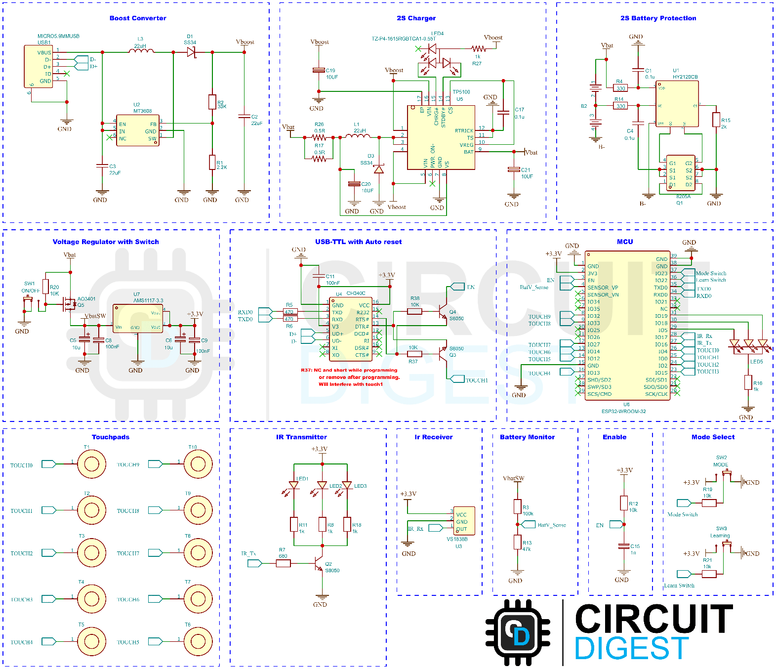
The complete schematic diagram for the Smart Universal Remote control is given below.

Here is the fully assembled smart remote.

Now let’s discuss each of the sections. The 5V input from the USB connector is connected to a Boost converter circuit built around the popular MT3608 IC from XI'AN Aerosemi Tech. The MT3608 is a constant frequency, 6-pin SOT23 current mode step-up converter intended for small, low-power applications. The MT3608 switches at 1.2MHz and this allows the use of tiny, low-cost capacitors and inductors. Internal soft-start results in a small inrush current and extends battery life. The MT3608 features automatic shifting to pulse frequency modulation mode at light loads. The MT3608 includes under-voltage lockout, current limiting, and thermal overload protection to prevent damage in the event of an output overload. Since we are using a 2S battery configuration, we will need at least 8.4V to fully charge our batteries. That’s why we are using this boost converter circuit to boost the 5V input to 8.4V. You can change the output voltage of the boost converter by changing the values of resistors R1 and R2.

The charger circuit is built around the TP5100 charging IC from TOPPOWER. TP5100 is a step-down switching double 8.4V / 4.2V single lithium battery charge management chip in an ultra-small QFN16 package. It requires a very minimal external circuit which makes it ideal for portable devices. Meanwhile, TP5100 has built-in input overcurrent, under-voltage protection, over-temperature protection, short circuit protection, battery temperature monitoring, and reverse battery protection. TP5100 can handle a wide input voltage of 5V-18V. The charge current can be adjusted through an external resistor. The maximum charging current is 2A. TP5100 uses a switching frequency of 400KHz.
A RGB LED in the 1615 package is used as a charging indicator. The charging current is set below 500mA to make sure the MT3608 is not overdriven, which would result in overheating. The charging current can be adjusted by changing the value of Resistors R17 and R26.

The battery protection circuit is based on the HY2120CB from HYCONTEK. This chip along with 8205A dual N-Channel MOSFET will protect the battery from over-discharge, overcharge, and accidental short circuit situations. This is the most common configuration you can find on most commercially available 2S BMS solutions.

The following section contains the 3.3V voltage regulator and the power switch. The output from the BMS is connected to a P-Channel MOSFET and the MOSFET gate is controlled to power the rest of the circuit. This approach is used since the small SMD slide switch can’t handle a current of more than 300mA. When we connect the gate of the MOSFET to a 0V level, the MOSFET will turn on and the current will pass through. A pullup resistor is used to ensure the MOSFET is fully turned OFF. AO3401 MOSFET from ALPHA & OMEGA Semiconductors is used since they are available in a small SOT-23 package and can handle a current up to 4A with very low RDS(On) of 85mΩ at 2.5V Vgs. The 3.3V for the SoC is made using the popular AMS1117-3.3 LDO. Sufficient bypass capacitors are used to eliminate any possible noise.

The programming circuit is made around the CH340C USB – TTL IC from WCH. The C variant doesn’t require an external crystal, and this will help save precious board space and will give better performance. The ESP32 auto-reset circuit is made with two NPN transistors. One thing to keep in mind is that since the GPIO0 is one of the touch inputs, the auto-reset circuit will interfere with the touch readings. We can avoid this by not installing the resistor R37. If you don’t install this resistor, you must short the resistor pads during the programming using a tweezer and remove that after the programming starts. Another workaround is to install the resistor and remove it after the initial programming. The future updates can be done over OTA.

The heart of this project is the ESP32-WROOM-32 module. The basic connections for the ESP32 are given below. An RGB LED is used here for notifications and mode indications.

The IR transmitter section consists of three IR LEDs along with the current limit resistors and a driver transistor. The transistor is driven with the PWM signal from GPIO16. The receiver is simple a VS1838 IR sensor and is connected to the GPIO17 pin.

Battery voltage monitoring is done using a voltage divider, which will translate the high battery voltage to a safe voltage level below 3.3V. The Smart Remote has three operational modes and can be selected using the two slide switches. More details are provided in the operation instruction below.

Finally, the 10 touch pads are used to detect each corresponding touch. The pads are Arranged neatly for better visual appeal and ease of use.

DIY Smart Universal Remote PCB Design
The PCB for the Smart IR Remote has a dimension of 145mm x 50mm. The image below shows the top side of the two-layer PCB. The top side has only two indicator LEDs. One on the bottom, near the USB port, will show the charging status and the other one on the top will show the mode status and other indications.

And here is the bottom side. The PCB is designed in a way that most of the components are on the bottom side. This will not only make the assembly process easier and cheaper, but the top side will look neat and clean.

You can download the PCB Layout, Gerber, and other supporting files from the project page Universal Smart Remote.
Assembling the Smart Universal Remote Control PCB
After the board was ordered, it reached me after some days through our courier service in a neatly labelled well-packed box. The PCB quality was good as always. The top layer and the bottom layer of the board are shown below:

After making sure the tracks and footprints were correct. I proceeded with the assembling of the PCB. The completely soldered board looks like the image below:


Now, we can move on to the next step which is configuring Adafruit IO and IFTTT
Setting Up Adafruit IO and IFTTT for Google Assistant Integration
As we have already mentioned, this Smart Remote supports Google Assistant Voice Command. For the Google Assistant integration, we are going to use the Adafruit IO and the IFTTT. So to start, go to Adafruit IO and create an account. If you already have an account login into it. Once logged in, go to the Dashboards page and create a new dashboard. Once created, open that dashboard and create a block by selecting the Create New Block option from the settings menu.

In the Create New Block wizard choose text block and in the Connect a feed window, create a new feed called Smart Remote as shown below.

Click on Next Step and in the next window enter the block title and click Create Block to finish. This will add a text block to your dashboard. Once it’s done, click on the My Key link at the top of the dashboard and copy your USERNAME and KEY. Add this to the Arduino code.
Now to set up IFTTT, go to the IFTTT website and create a new account or login into the existing account. Once Logged in, click on the Create button on the top. In the Create Applet widget, select Google Assistant for If This and connect the same Google account you’re using on your phone when asked. In the next window, set everything as shown below and click save.

And for Then That select Send data to Adafruit IO template and link your Adafruit IO account when asked. And in the setting select the Smart remote feed you have previously created and add a text field ingredient as shown below.

Then click on save and that’s all.
Arduino Code for Smart Remote
Download the entire code from the Circuit Digest GitHub repo link given at the bottom of this article. Extract it to a folder and make sure not to change any file or folder structure. All the necessary libraries and files are included in the sketch folder. Open the sketch in the Arduino IDE and select ESP32 Dev Module as the board. Also, set the partition scheme to Minimal SPIFFS (1.9MB APP with OTA/109KB SPIFFS).

Add your Adafruit IO username and key to the sketch. Then compile the code and upload it.

And while programming, if you haven’t installed the R37 resistor, you must short the resistor pads during the programming using a tweezer and remove that after the programming starts. And if you have installed it, remove it as soon as the programming is done.
Smart Remote Operation Instruction

The Smart Remote has three operation modes namely Learning Mode, Smart Mode, and Power Saving Mode. You can select the mode using the two slide switches on board. Please check the image below to know how to select each mode. Keep in mind that you should change to Smart / Power saving once the learning or IR training is done.

Now let’s see how each mode works and how to operate in each mode.
Learning Mode
In this mode, we can store code for each touch input. To enter learning mode, change the Learning mode switch to its down position, and the status LED will show an RGB pattern to indicate that the remote is in the learning mode. To train or store the IR code, touch on the corresponding touchpad, and press the switch on the other remote you want to learn, pointing to the IR receiver as shown below. Once valid code is stored the RGB LED will flash an RGB pattern indicating the code is saved. Repeat this process for all other touchpads and change the Learning to the upward position once done.
Smart Mode
In the smart mode, you can operate the remote in three ways. By directly touching the corresponding touchpad, by using a smartphone or by using the Google Assistant Voice command. To use the Smart mode, make sure the learning mode is off and put the other mode selection switch to the downward position. The RGB LED will blink in red colour while booting to indicate that the remote is in Smart mode. And the LED will stay on in red colour.
During the initial set-up or if the remote Wi-Fi settings are reset, the Remote will change to configuration mode. During this, the touch pads won’t work. To configure the remote, use a smartphone to connect to the Wi-Fi hotspot named Smart Remote. The password for the hotspot is circuitdigest.

Once connected the following page will open automatically. Click on Configure WiFi.

In a few seconds, a new page will open showing all the available networks. You can either select one or enter the SSID manually.

Once the password is entered, click on Save to save the WiFi configuration.

Once done, after a few seconds turn off and turn on the remote. The Smart remote will connect to the WiFi you have configured. If the WiFi connection is failed the remote will go to the configuration mode and you can set the WiFi settings again. This setup is only necessary at once. The remote will connect to the WiFi network automatically after this.
Once the initial setup is complete, you can access the remote through any web browser. If you are using an Apple device or a PC, you can access the remote by going to the following address http://smartremote.local/. If you’re using an Android device, you can access the remote by entering the device’s IP address. You can find this IP address either from your router or by connecting it to the PC and opening the Serial monitor and then rebooting. You can also use any network scanning app to find the IP.

You can operate the remote by pressing any button on the resulting webpage. The touch pads will also work so that you can use the remote simultaneously. You can operate the remote with Google Assistant voice command too. For this, make sure your WiFi has internet access. To use the Voice command, make sure you’re using the same Google account on your phone, which you have linked to the IFTTT applet. To operate, simply say “OK Google, Send button next” or “Hey Google, Send button next”. Change the last phrase to the corresponding keyword. The current keywords are power, ok, Up, Down, Left, Right, Plus, Minus, Next, and Previous. You can change or customize these phrases in the Arduino code if you like.
Power Saving Mode
In this mode, the remote will work as a normal remote. The WiFi and other smart functions will be disabled. You can operate the remote with the touchpad. The remote will go to deep sleep mode if it’s not used for 20 seconds to save power and will wake automatically when you touch touchpads.
Resetting the Smart Remote
You can reset the remote if you want to reset the WiFi configurations. To do this, make sure the remote is in Smart mode. Turn off the device. Turn it back on while touching and holding power, minus, and previous buttons. Keep the touch until you see the LED flash in red and blue colour alternatively. Once the LED starts to flash, release the touch and touch the OK button to confirm reset. The Remote will clear all the WiFi configurations and will go into configuration mode. Now you can set the WiFi configurations as mentioned earlier.
Updating the Smart Remote
To make the Smart Remote, we have included the OTA firmware update. You can update your Smart Remote’s firmware from any browser, and it is pretty easy too. To update the firmware, first, make sure the Smart Remote is in smart mode and the smartphone or computer you’re using to update the firmware is connected to the same network as the Smart Remote. Then go to the update URL http://ip_address/update. Replace the ip_address with the IP address of the Smart Remote, for eg example the IP address of my smart remote is 192.168.29.246 so the OTA update URL of my Smart Remote will be http://192.168.29.246/update.
If you are using an Apple device or a computer, you can also access the OTA update page by going to the MDNS address http://smartremote.local/update. Keep in mind that this address won’t work with all Android phones since the older Android Versions don’t support MDNS. On the update page, make sure the Firmware radio option is selected. Then click on the Choose File button and select your firmware bin file. Once a valid firmware file is selected, the Smart Remote will be automatically updated to it.

Once the update is complete and successful, the Smart Remote will automatically reboot.

Charging the Smart Remote
You can charge the remote by simply connecting the USB cable from any 5V charger to the micro-USB port at the bottom. The charging indicator will glow in red, indicating that the device is being charged. Once fully charged the LED will change to blue.
Smart Universal Remote with Learning Function and Google Assistant Support
*PCBWay community is a sharing platform. We are not responsible for any design issues and parameter issues (board thickness, surface finish, etc.) you choose.
- Comments(1)
- Likes(2)
- 0 USER VOTES
- YOUR VOTE 0.00 0.00
- 1
- 2
- 3
- 4
- 5
- 6
- 7
- 8
- 9
- 10
- 1
- 2
- 3
- 4
- 5
- 6
- 7
- 8
- 9
- 10
- 1
- 2
- 3
- 4
- 5
- 6
- 7
- 8
- 9
- 10
- 1
- 2
- 3
- 4
- 5
- 6
- 7
- 8
- 9
- 10
 More by Jobit Joseph
-
 How to build a Wearable Air Quality Monitor Pendant using STM32 & SGP40 Sensor
This DIY Wearable Air Quality Monitor Pendant is a compact, battery-powered device designed to conti...
-
 Smart Digital Ludo Game Board with Multicolour PCB
Ludo, a beloved childhood game, holds a special place in our hearts with its simple and engaging gam...
-
 Electronic Dice with BLE Connectivity
Many of us fondly remember the joy of playing board games like Snakes and Ladders or Ludo during our...
-
 3D printed Enclosure Backplate for Riden RD60xx power supplies
3D printed Enclosure for Riden RD60xx power supplies such as RD6006, RD6012, RD6018, RD6024 and RD60...
-
 3D printed Enclosure for Riden RD60xx power supplies
 such as RD6006, RD6012, RD6018, RD6024 and RD60...
3D printed Enclosure for Riden RD60xx power supplies
3D printed Enclosure for Riden RD60xx power supplies such as RD6006, RD6012, RD6018, RD6024 and RD60...
-
 Suzuki Ignis Universal Armrest No Screw Adapter
I own a 2024 Suzuki Ignis. When I searched for an armrest for my car I couldn't find any domesticall...
-
 Wireless Potentiostat for Electrochemical Analysis
This wireless potentiostat is based on the ADuCM355 SoC from Analog Devices, tailored for portable e...
-
 160 Channel Configurable DAC Controller
The DAC controller board features 160 individually controllable 16-bit DAC output. It can output vol...
-
 Build Your Own Precision Digital Micro-Current Meter with STM32
In many electronic projects — especially those involving battery-powered devices or low-power sensor...
-
 DIY Meshtastic Using ESP32 : Build Your Own Private Off-Grid Network
Project OverviewThis project delivers a complete, custom-designed PCB solution for building Meshtast...
-
 Second PCB for ESP32 Smart Watch
This project contains two PCBs, this is the Second PCB,and there is a Main PCB, please click https:/...
-
 1S battery Charger with Battery level indicator and power path
1S Battery Charger with Battery level indicator and 5V out and standby mode.
-
 Smart Universal Remote with Learning Function and Google Assistant Support
In our day-to-day life, we use various gadgets such as televisions, set-top boxes, air conditioners,...
-
 High-Resolution POV Display using ESP32
In this guide, we'll learn how to create a cool POV display using an ESP32 module. It's all about us...
-
 Low Cost Drone using ESP32
Drones have rapidly evolved from niche hobbies to versatile tools with a wide range of applications,...
-
 DIY Thermal Camera
Ditch X-ray vision, thermal cameras are the real industrial superheroes! They don't just see light, ...
-
 ESP32 Smart Watch
This project contains two PCBs, this is the Main PCB, and there is a Second PCB, please click https:...
-
 ESP32 S3 Touch Screen Console for IoT and HMI applications
Welcome to the ESP32 Touch Screen Console project for IoT and HMI applications! In this project, we ...
-
-
AEL-2011 Power Supply Module
513 0 2 -
AEL-2011 50W Power Amplifier
473 0 2 -
-
-
Custom Mechanical Keyboard
688 0 0 -
Tester for Touch Screen Digitizer without using microcontroller
321 2 2 -
Audio reactive glow LED wristband/bracelet with NFC / RFID-Tags
306 0 1 -
-
-


