|
KiCADKicad
|
Infrared Remote-Controlled Module for Home Appliances
Introduction
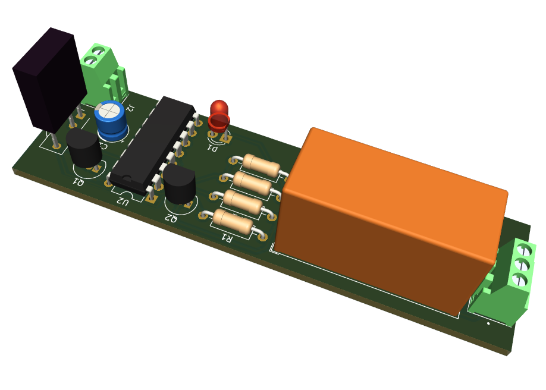
The Infrared (IR) Remote Control Switch Circuit offers a cost-effective solution for managing household appliances in our fast-paced lives. Consequently, there is significant emphasis on this technology, resulting in various remote-control options available today. Among the most common is one that utilises IR radiation at specific frequencies to operate devices. Therefore, this guide will demonstrate creating an "Infrared IR Remote Control Relay Module" using TSOP1713 and the CD4017 Decade Counter IC.
This circuit serves as a remote-operated home appliance control system. It can be connected to various household appliances such as lamps, fans, radios, etc., enabling them to be turned on/off using a TV, VCD, VCR, air conditioner, or DVD remote control. The circuit can be activated from a distance of up to 8 meters and is straightforward to construct, suitable for assembly on a standard prototype PCB.
Components
- C1 1 1uF C_Polarized_Small_US Capacitor_THT:CP_Radial_D5.0mm_P2.50mm Polarized capacitor, small US symbol
- D1 1 LED_Small LED_Small LED_THT:LED_D3.0mm Light emitting diode, small symbol
- D2 1 1N4007 1N4007 Diode_THT:D_DO-41_SOD81_P10.16mm_Horizontal 1000V 1A General Purpose Rectifier Diode, DO-41 J1 1 Screw_Terminal_01x03 Screw_Terminal_01x03 282834-3:TE_282834-3 Generic screw terminal, single row, 01x03, script generated (kicad-library-utils/schlib/autogen/connector/)
- J2 1 Screw_Terminal_01x02 Screw_Terminal_01x02 282834-2:TE_282834-2 Generic screw terminal, single row, 01x02, script generated (kicad-library-utils/schlib/autogen/connector/)
- K1 1 RT314A06 RT314A06 Relay_THT: Relay_SPDT_Schrack-RT1-16A-FormC_RM5mm Schrack RT1 relay, bistable-single pole dual throw, single DC coil, 6V
- Q1 1 BC557 BC557 Package_TO_SOT_THT:TO-92_Inline 0.1A Ic, 45V Vce, PNP Small Signal Transistor, TO-92
- Q2 1 BC547 BC547 Package_TO_SOT_THT:TO-92_Inline 0.1A Ic, 45V Vce, Small Signal NPN Transistor, TO-92
- R1 1 10k R_Small_US Resistor_THT:R_Axial_DIN0207_L6.3mm_D2.5mm_P10.16mm_Horizontal Resistor, small US symbol R2 1 100k R_Small_US Resistor_THT:R_Axial_DIN0207_L6.3mm_D2.5mm_P10.16mm_Horizontal Resistor, small US symbol R3 1 220 R_Small_US Resistor_THT:R_Axial_DIN0207_L6.3mm_D2.5mm_P10.16mm_Horizontal Resistor, small US symbol R4 1 1k R_Small_US Resistor_THT:R_Axial_DIN0207_L6.3mm_D2.5mm_P10.16mm_Horizontal Resistor, small US symbol U1 1 TSOP17xx TSOP17xx OptoDevice:Vishay_CAST-3Pin Photo Modules for PCM Remote Control Systems
- U2 1 4017 4017 Package_DIP:DIP-16_W7.62mm Johnson Counter ( 10 outputs )
Infrared Remote Control Circuit

How it Works
The circuit uses an infrared remote control, which produces infrared rays at 38 kHz. The IR receiver module TSOP 1738 detects these rays. This module, pin1 is connected to the ground, pin2 to the power supply, and pin3 to the output signal through a 10k resistor labeled R1. A transistor Q1 (BC557) is used to boost the output signal. The amplified signal is then routed to the decade counter IC CD4017 (IC1)'s clock pin 14. The ground supply is connected to pin 8 of IC1, while the Vcc supply is attached to pin 16.
Pin2 of IC1 is used to retrieve its output. A red LED is connected to pin 2 to signify the device's 'on' status. The base of transistor Q2 (BC547) is linked to pin 2 of IC1, acting as a relay driver and a switching mechanism. The appliance to be controlled is linked to the relay's pole and the neutral terminal of the power supply. When the relay gets an input, it connects the appliance to the AC mains live terminal through its Normally Open (N/O) contact. As a result, pressing the remote control toggles the relay, allowing any connected device to be turned on or off.

Installation Process
Firstly, the relay is soldered, followed by the output terminal block and the IC base. Afterwards, the diode and the transistor are soldered. After that, insert every resistor by soldering them, followed by soldering the TSOP1738. The output connector is then soldered, and an AC bulb is added cautiously to series with the output. Finally, the circuit is tested.
Uses
The TSOP1738 & CD4017 infrared remote control relay module is used in various fields, including wireless controlling, communicating over extended distances, and managing household devices such as fans, refrigerators, and televisions.

How to Use Such a Board
This board can be manufactured through PCBWay. Besides manufacturing, the board can be used with other development boards like Arduino and Raspberry Pi. These crucial modules can be purchased through PCBWay, too, through ordering at the product menu page. You can receive such boards as a gift, buy them using coupons, redeem your reward points, or deposit money into your PCBway account and order directly.

Infrared Remote-Controlled Module for Home Appliances
*PCBWay community is a sharing platform. We are not responsible for any design issues and parameter issues (board thickness, surface finish, etc.) you choose.
- Comments(0)
- Likes(0)
- 0 USER VOTES
- YOUR VOTE 0.00 0.00
- 1
- 2
- 3
- 4
- 5
- 6
- 7
- 8
- 9
- 10
- 1
- 2
- 3
- 4
- 5
- 6
- 7
- 8
- 9
- 10
- 1
- 2
- 3
- 4
- 5
- 6
- 7
- 8
- 9
- 10
- 1
- 2
- 3
- 4
- 5
- 6
- 7
- 8
- 9
- 10
 More by Simon Mugo
-
 High Power Three Channel LED Driver
IntroductionI have been thinking about how to drive RGB LED patterns most simply. In my day-to-day r...
-
 433 MHz Radio Frequency Transmitter Module
IntroductionTwo devices can communicate with each other using radio frequencies and using an RF tran...
-
 Customized Servo Motor Driver Board
IntroductionServo motors, also called rotary or linear actuators, are designed for minimal control o...
-
 Arduino Customized L298M Dual Motor Driver Module
IntroductionThe Arduino Customized L298M Dual Motor Driver Module is designed to handle high-power D...
-
 Overvoltage Protection Board
PrecautionBefore making use of the circuit in this design project, ensure that you first set the var...
-
 Automatic Residential Lighting System Board Based on AT89C51
In our day-to-day activities, we often don't remember to switch off or on the lights in our rooms. T...
-
 The Energy Saving Bulb Board
The traditional incandescent bulb is an energy waster and it should be removed off shelves. My new t...
-
 ESP8266 MINI TEST BOARD
Design Of The SchematicThe schematic design is done in KiCAD. The process starts with finding the da...
-
 POWER SUPPLY FOR THE ESP8266
ESP8266 is a microchip of low cost that is produced by a company by the name of ESPPRESSIF stems. It...
-
 1N4148 INCOPORATING 741 IC TEMEPERATURE SENSOR
Creating a simple temperature sensor using a diode (1N4148) and an operational amplifier (741 IC) is...
-
 TSL25911 Light Sensor
IntroductionWe interact with different intensities and strengths of light in our daily activities. T...
-
 SIM800 GPS module
ElevatorThis project demonstrates how you can develop various GPS/ GPRS and SMS capability developme...
-
 nRF51822 Mini Evaluation Board
IntroductionDemand for development and evaluation boards the world over has increased. Due to such d...
-
 Customized LM393D Soil Moisture Sensor Board
ElevatorThe project is good at converting analog signals from the soil to digital signals for soil m...
-
 PAM8403 Amplifier Module
IntroductionThis is a simple project for improving your musical or audio entertainment by powering y...
-
 741 IC Bass Booster
IntroductionIn this project, we are going to design a bass booster circuit using the 741 IC. This is...
-
 LM317 AND LM337 ADJUSTABLE POWER SUPPLY CIRCUIT BOARD
IntroductionThe LM317/LM337 symmetrical power supply circuit is an electronic setup for meeting the ...
-
 230V AC to 1.5V DC PCB for Your Application
IntroductionA power management integrated circuit (PMIC) is utilized to supply the necessary power t...
-
Build a Walking Robot: Theo Jansen Style 3D Printed Octopod
154 0 4 -
-
-
kmMiniSchield MIDI I/O - IN/OUT/THROUGH MIDI extension for kmMidiMini
142 0 0 -
DIY Laser Power Meter with Arduino
221 0 3 -
-
-
Box & Bolt, 3D Printed Cardboard Crafting Tools
191 0 2


