|
Autodesk Fusion 360Autodesk
|
|

|
arduino IDEArduino
|
MacTEMPtosh
Greetings.
So this is the Mini MacTEMPtosh, a portable Temperature and Humidity meter that displays the current Temp and Humidity level by an onboard AHT10 Sensor.

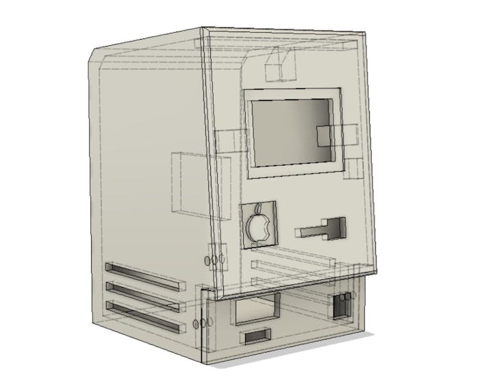
Its Body is made to look like the old MACINTOSH 128K Desktop PC so that's why it's called MacTEMPtosh.
This setup is powered by an ESP32 Board and has a Lithium Cell as the power source.
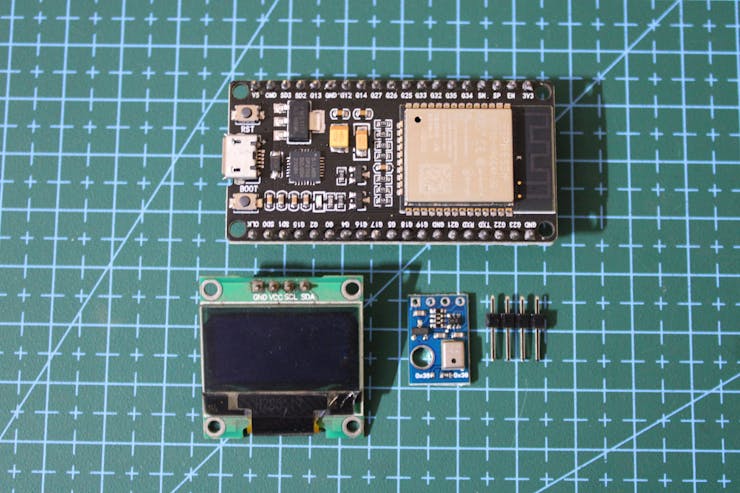
AHT10 is being used to measure the current TEMP and Humidity level that is being displayed on an SSD1306 OLED Display which is all controlled by an ESP32 Board.
This Article is about the whole built process of this device so let's get started.
Material Required
Following were the materials used in this built-
- ESP32
- SSD1306
- AHT10 Temp Sensor
- IP5303 Module
- Li-ion Cell
- 3D Printed parts
- header pins and connection wires
Concept
We start first by conceptualizing the whole setup that will look kinda like a MAC 128K Desktop from 1984.
By Taking inspiration from the real MAC 128K Desktop, I prepared the whole body which was made in three parts that are the front cover, the lower part, and the base body.
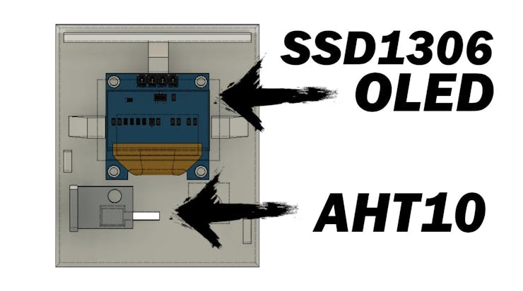
Front Cover holds the SSD1306 Display and AHT10 Temperature sensor in their place, SSD1306 is placed on the display window and the AHT Temp sensor is placed in the slot given for false floppy slit.
The lower part holds the IP5303 Module and the ON-OFF Switch.
The Base body contains the Li-ion Cell and ESP32 board, we screw the front cover and lower part it with through screws.
As for the electronics part, ESP32 is being used to drive the SSD1306 Display and AHT10 temperature and humidity sensor.
PCBWAY Giftshop
As for sourcing the electronics for this project, I got the ESP32 Wroom Development board from PCBWAY's Giftshop along with the AHT10 Temperature and Humidity Sensor.
Aside from PCB and CNC Related services, PCBWAY also has an online marketplace for getting bunches of electronics-related stuff like DEV Boards, Sensors, Modules, and all kinds of DIY Boards.
PCBWAY have this system that lets us purchase anything from their gift shop through beans, Beans are like a redeemable currency or coupons that we get by placing an order on PCBWAY or by sharing your projects in the community to get beans.
Check PCBWAY out for getting great PCB service from here- https://www.pcbway.com/
Basic Breadboard Setup
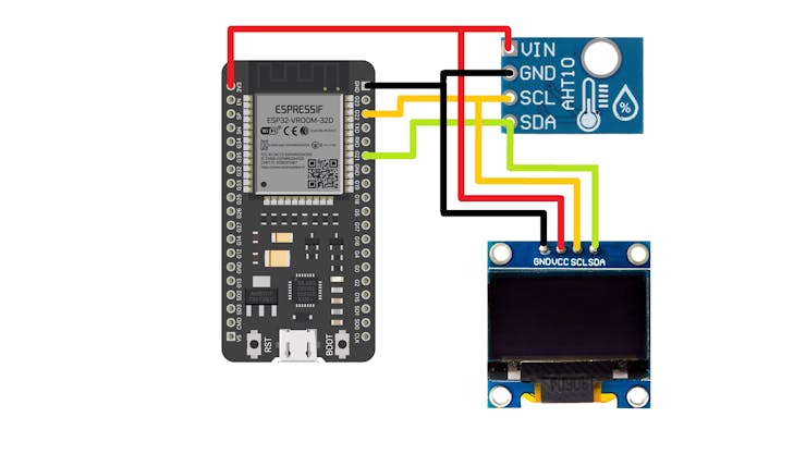

We first prepare the Breadboard setup by connecting the ESP32 with SSD1306 Display and AHT10 sensor by following the provided wiring diagram.
AHT10 and SSD1306 both work with I2C so they share the SCK and SDA Pins of the ESP32.
Because ESP32 have a big format factor, it cannot be put on a single breadboard for prototyping so I used two breadboard side by side for mounting the ESP32 board.
Power Source- IP5303 Module
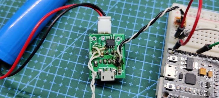

For powering the whole setup, we use a single Li-ion cell whose nominal voltage is 3.7V which is not sufficient to power the ESP32 with display and sensor.
To Boost the voltage from 3.7V to 5V, we use the IP5303 Module which is a power management board that is commonly used in power banks.
Read more about the IP5303 Module from my previous article-
https://www.hackster.io/Arnov_Sharma_makes/li-ion-boost-module-for-raspberry-pi-6b2233
To keep things simple and short, this module steps up 3.7V to 5V DC (stable voltage) and provides suitable discharging and charging cutoff features as well that control the low cut and high cut of a lithium cell, this feature prevents the cell to get overcharged or over-discharge.
We connect the IP5303 Module with the breadboard setup by connecting the 5V to VS of the ESP32 board and GND to GND.
The lithium Cell that is being used is the standard 18650 Li-ion cell 3.7V 2200mAh.
There wasn't any button or key on the PCB for turning it ON, so I added a tactile switch with PIN5 through a 10k Resistor in series with GND. when we press this button, it pulls down the PIN5 and the module activates, double tap, and the module deactivates.
CODE
Here's the main code.
#include <Wire.h> #include <AHTxx.h> #include <Wire.h> #include <Adafruit_GFX.h> #include <Adafruit_SSD1306.h> #define SCREEN_WIDTH 128 // OLED display width, in pixels #define SCREEN_HEIGHT 64 // OLED display height, in pixels Adafruit_SSD1306 display(SCREEN_WIDTH, SCREEN_HEIGHT, &Wire, -1); float ahtValue; //to store T/RH result AHTxx aht10(AHTXX_ADDRESS_X38, AHT1x_SENSOR); //sensor address, sensor type void setup() { display.begin(SSD1306_SWITCHCAPVCC,0x3C); display.clearDisplay(); #if defined(ESP8266) WiFi.persistent(false); //disable saving wifi config into SDK flash area WiFi.forceSleepBegin(); //disable AP & station by calling "WiFi.mode(WIFI_OFF)" & put modem to sleep#endif Serial.begin(115200); Serial.println(); while (aht10.begin() != true) //for ESP-01 use aht10.begin(0, 2); { Serial.println(F("AHT1x not connected or fail to load calibration coefficient")); //(F()) save string to flash & keeps dynamic memory free delay(10000); } Serial.println(F("AHT10 OK")); } void loop() { Serial.println(); Serial.println(F("DEMO 1: read 12-bytes")); ahtValue = aht10.readTemperature(); //read 6-bytes via I2C, takes 80 milliseconds display.display(); display.setTextSize(2); display.setTextColor(WHITE); display.setCursor(1, 0); display.println(F("TEMP C")); display.display(); display.setTextSize(3); display.setTextColor(WHITE); display.setCursor(0, 35); display.println(ahtValue); display.display(); display.clearDisplay(); delay(20000); ahtValue = aht10.readHumidity(); //read another 6-bytes via I2C, takes 80 milliseconds display.setTextSize(2); display.setTextColor(WHITE); display.setCursor(1, 0); display.println(F("Humidity %")); display.display(); display.setTextSize(3); display.setTextColor(WHITE); display.setCursor(0, 35); display.println(ahtValue); display.display(); display.clearDisplay(); delay(20000); } void printStatus() { switch (aht10.getStatus()) { case AHTXX_NO_ERROR: Serial.println(F("no error")); break; case AHTXX_BUSY_ERROR: Serial.println(F("sensor busy, increase polling time")); break; case AHTXX_ACK_ERROR: Serial.println(F("sensor didn't return ACK, not connected, broken, long wires (reduce speed), bus locked by slave (increase stretch limit)")); break; case AHTXX_DATA_ERROR: Serial.println(F("received data smaller than expected, not connected, broken, long wires (reduce speed), bus locked by slave (increase stretch limit)")); break; case AHTXX_CRC8_ERROR: Serial.println(F("computed CRC8 not match received CRC8, this feature supported only by AHT2x sensors")); break; default: Serial.println(F("unknown status")); break; } }
This sketch utilizes the below libraries that you first need to install.
#include <Adafruit_GFX.h> #include <Adafruit_SSD1306.h> #include <AHTxx.h>
RESULT So Far...

First, Temperature Readings get displayed on the SSD1306 Display for 20 seconds, then Humidity data get displayed and this process switches back and forth.
AHT10 reads the temperature data through MEMS technology which is basically a tiny integrated device for reading all kinds of data (Temp in this case) through elements present on the chip.
3D Printing process

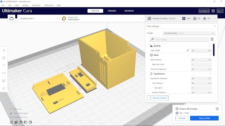
As for the 3D Printing Process, we export Mesh files from the Fusion360 Model and open them in CURA for slicing.
I used a 0.4mm Nozzle with 0.2mm Layer height with an infill of 20%, the usual settings.
PLA was used for preparing these prints.
WIRING


- Before the main assembly, we first add wires between ESP32, SSD1306, and Temp Sensor by following the wiring diagram.
- We connect two con4 header pin sockets with wires for SSD1306 and TEMP Sensor and connect their wires with ESP32, SSD1306 and Temp Sensor can be removed from their wiring mesh because we use connectors for their header pin.
- We solder the wire directly on ESP32 so it will be easy to place and connect during the assembly process.
- After finalizing the wiring, we add IP5303 Setup with the ESP32 by soldering its VCC and GND to ESP32's VS and GND.
ASSEMBLY of Front Cover and Lower Part


- The Assembly process consists of a few steps that first require preparing the Front Cover assembly by adding SSD1306 Display in its place along with the AHT10 Temp sensor. we add hot glue to hold AHT10 Sensor in its place.
- Next, we add the IP5303 Module on the lower part with hot glue and also add the ON-OFF Toggle switch in its provided square slot.
Connecting ESP32 with Front and Lower part


- Next, we add the ESP32 Setup with Display and Temp sensor by plugging the header pin socket back on the SSD1306 and AHT10 header pin.
- We then plug the battery in the JST Connector which was on the IP5303 Setup.
- Next, we check the setup by using the ON-OFF Switch and checking if this setup works or not, display lights up and starts displaying the current Temp and humidity.
Final Assembly


- The final assembly consists of putting everything together by adding lithium cells to the base body and then placing the ESP32 board on another side.
- we then add the Front and lower parts in their place.
- At last, we secure everything together by using four M2 Screws.
RESULT

Here's the finished project, a working mini Macintosh-inspired Temperature and humidity meter that keeps track of current room Temp and humidity %.
MacTEMPtosh is now ready, to turn it ON, we press the Button once.
By double tapping the Button, it turns OFF.

It also has an auto shut down feature that turns this setup OFF after 30 Seconds, this saves battery and this setup can run for days with this setting.
This is it for today folks, if you have any problem regarding this project, leave a comment.
Special thanks to PCBWAY for supporting this project, you guys can check them out for getting great PCB Service for less cost.
Stay tuned for the next project!
Peace
#include <Wire.h>
#include <AHTxx.h>
#include <Wire.h>
#include <Adafruit_GFX.h>
#include <Adafruit_SSD1306.h>

#define SCREEN_WIDTH 128 // OLED display width, in pixels
#define SCREEN_HEIGHT 64 // OLED display height, in pixels

Adafruit_SSD1306 display(SCREEN_WIDTH, SCREEN_HEIGHT, &Wire, -1);

float ahtValue;                               //to store T/RH result

AHTxx aht10(AHTXX_ADDRESS_X38, AHT1x_SENSOR); //sensor address, sensor type


void setup()
{

  display.begin(SSD1306_SWITCHCAPVCC,0x3C);
  display.clearDisplay();

  #if defined(ESP8266)
  WiFi.persistent(false);  //disable saving wifi config into SDK flash area
  WiFi.forceSleepBegin();  //disable AP & station by calling "WiFi.mode(WIFI_OFF)" & put modem to sleep
  #endif

  Serial.begin(115200);
  Serial.println();

  while (aht10.begin() != true) //for ESP-01 use aht10.begin(0, 2);
  {
    Serial.println(F("AHT1x not connected or fail to load calibration coefficient")); //(F()) save string to flash & keeps dynamic memory free

    delay(10000);
  }

  Serial.println(F("AHT10 OK"));

}

void loop()
{
  Serial.println();
  Serial.println(F("DEMO 1: read 12-bytes"));

  ahtValue = aht10.readTemperature(); //read 6-bytes via I2C, takes 80 milliseconds

    display.display();
    display.setTextSize(2);
    display.setTextColor(WHITE);
    display.setCursor(1, 0);
    display.println(F("TEMP C"));
    display.display();

    display.setTextSize(3);
    display.setTextColor(WHITE);
    display.setCursor(0, 35);
    display.println(ahtValue);
    display.display();

    display.clearDisplay();
    delay(20000);


 ahtValue = aht10.readHumidity(); //read another 6-bytes via I2C, takes 80 milliseconds


    display.setTextSize(2);
    display.setTextColor(WHITE);
    display.setCursor(1, 0);
    display.println(F("Humidity %"));
    display.display();

    display.setTextSize(3);
    display.setTextColor(WHITE);
   display.setCursor(0, 35);
    display.println(ahtValue);
    display.display();

    display.clearDisplay();
    delay(20000);
}

void printStatus()
{
  switch (aht10.getStatus())
  {
    case AHTXX_NO_ERROR:
      Serial.println(F("no error"));
      break;

    case AHTXX_BUSY_ERROR:
      Serial.println(F("sensor busy, increase polling time"));
      break;

    case AHTXX_ACK_ERROR:
      Serial.println(F("sensor didn't return ACK, not connected, broken, long wires (reduce speed), bus locked by slave (increase stretch limit)"));
      break;

    case AHTXX_DATA_ERROR:
      Serial.println(F("received data smaller than expected, not connected, broken, long wires (reduce speed), bus locked by slave (increase stretch limit)"));
      break;

    case AHTXX_CRC8_ERROR:
      Serial.println(F("computed CRC8 not match received CRC8, this feature supported only by AHT2x sensors"));
      break;

    default:
      Serial.println(F("unknown status"));
      break;
  }
}

MacTEMPtosh
*PCBWay community is a sharing platform. We are not responsible for any design issues and parameter issues (board thickness, surface finish, etc.) you choose.
- Comments(0)
- Likes(0)
- 0 USER VOTES
- YOUR VOTE 0.00 0.00
- 1
- 2
- 3
- 4
- 5
- 6
- 7
- 8
- 9
- 10
- 1
- 2
- 3
- 4
- 5
- 6
- 7
- 8
- 9
- 10
- 1
- 2
- 3
- 4
- 5
- 6
- 7
- 8
- 9
- 10
- 1
- 2
- 3
- 4
- 5
- 6
- 7
- 8
- 9
- 10
 More by Arnov Arnov sharma
-
 Pocket SNES
Greetings everyone, and welcome back! Today, I’ve got something fun and tiny to share—the Pocket SNE...
-
 Batocera Arcade Box
Greetings everyone and welcome back, Here's something. Fun and nostalgic. Right now, we are using ou...
-
 64x32 Matrix Panel Setup with PICO 2
Greetings everyone and welcome back.So here's something fun and useful: a Raspberry Pi Pico 2-powere...
-
 Portable Air Quality Meter
Hello everyone, and welcome back! Today, I have something incredibly useful for you—a Portable Air Q...
-
 WALKPi PCB Version
Greetings everyone and welcome back, This is the WalkPi, a homebrew audio player that plays music fr...
-
 Delete Button XL
Greetings everyone and welcome back, and here's something fun and useful.In essence, the Delete Butt...
-
 Arduino Retro Game Controller
Greetings everyone and welcome back. Here's something fun.The Arduino Retro Game Controller was buil...
-
 Super Power Buck Converter
Greetings everyone and welcome back!Here's something powerful, The SUPER POWER BUCK CONVERTER BOARD ...
-
 Pocket Temp Meter
Greetings and welcome back.So here's something portable and useful: the Pocket TEMP Meter project.As...
-
 Pico Powered DC Fan Driver
Hello everyone and welcome back.So here's something cool: a 5V to 12V DC motor driver based around a...
-
 Mini Solar Light Project with a Twist
Greetings.This is the Cube Light, a Small and compact cube-shaped emergency solar light that boasts ...
-
 PALPi V5 Handheld Retro Game Console
Hey, Guys what's up?So this is PALPi which is a Raspberry Pi Zero W Based Handheld Retro Game Consol...
-
 DIY Thermometer with TTGO T Display and DS18B20
Greetings.So this is the DIY Thermometer made entirely from scratch using a TTGO T display board and...
-
 Motion Trigger Circuit with and without Microcontroller
GreetingsHere's a tutorial on how to use an HC-SR505 PIR Module with and without a microcontroller t...
-
 Motor Driver Board Atmega328PU and HC01
Hey, what's up folks here's something super cool and useful if you're making a basic Robot Setup, A ...
-
 Power Block
Hey Everyone what's up!So this is Power block, a DIY UPS that can be used to power a bunch of 5V Ope...
-
 Goku PCB Badge V2
Hey everyone what's up!So here's something SUPER cool, A PCB Board themed after Goku from Dragon Bal...
-
 RGB Mixinator V2
Hey Everyone how you doin!So here's a fun little project that utilizes an Arduino Nano, THE MIXINATO...
-
-
mammoth-3D SLM Voron Toolhead – Manual Drill & Tap Edition
198 0 0 -
-
AEL-2011 Power Supply Module
727 0 2 -
AEL-2011 50W Power Amplifier
605 0 2 -
-
-
Custom Mechanical Keyboard
809 0 0 -
Tester for Touch Screen Digitizer without using microcontroller
437 2 2 -
Audio reactive glow LED wristband/bracelet with NFC / RFID-Tags
390 0 1 -
-


