|
|
arduino nano |
x 1 | |
|
|
dip8 socket |
x 6 | |
|
|
jumpers |
x 21 | |
|
|
leds |
x 4 |
Multiple ATtiny85/13A Programmer
Attiny MCUs are very popular as it is quite easy to program them and using them instead of atmega328 chip can reduce the cost of the overall project which requires less input/outputs.
STEP 1 - Designing the PCB
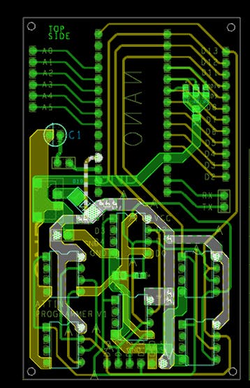
I designed this nano breakout board in OrCad Cadance, it has four LEDs (3 of them are connected to D7 D8 and D9 for ICSP programming status, and the fourth one is connected to D11 or D0 of attiny in case we need to test attiny onboard)
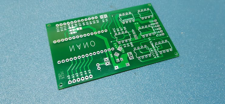
I send it to a PCB manufacturer (PCBWAY DUH) and got PCBs in 22 days (because of the pandemic situation)
STEP 2 - ASSEMBLY!
We just need the following things for this project-
- Arduino nano x1
- DIP8 Sockets x6
- 1uf 10V CAP x1
- male headers 28 to be exact
- LEDs 0603 package x4
- 1K Resistor 0805 package x2
- PCB
- 3D printed enclosure
- attiny85 x6
after gathering the above components, I just solder them all together and made this slick-looking Programmer.
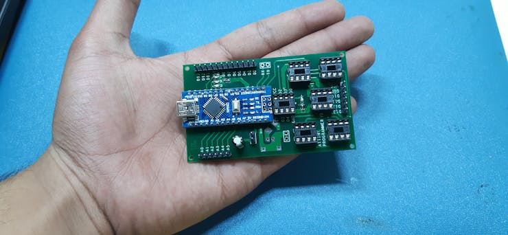
STEP 3 - Testing
first, I plugged the Arduino nano with my computer and flashed it with a simple Chaser led sketch which will toggle led connected to pin D7, 8, 9, and D11 in chaser order. left to right
After this, I uploaded "Arduino as icsp" sketch from example sketches to this board and shorted the jumper after the sketched was uploaded.
I plugged out the USB cable and bring out 6 attiny85, for programming.
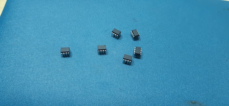
STEP 4 - Getting the Core files and Programming the ATTINY85/13A
now before programming the attiny85, we need to get its core from here- https://github.com/SpenceKonde/ATTinyCore
(just follow the installation process which is very thorough and simple)
after installing the core files, placed ATTINY in dip sockets carefully without applying too much pressure because guess what,
if you apply too much force, ATTINY legs will bend,
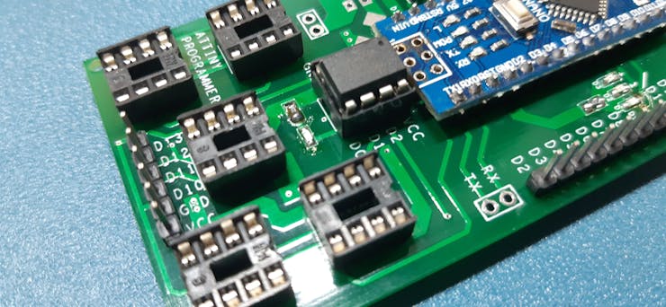
Now open Blink sketch or any other sketch that you want to flash it onto your attiny (I'm gonna flash blink sketch and output pin is D0)
STEP1
plug your attiny on DIP socket and get ready for programming,
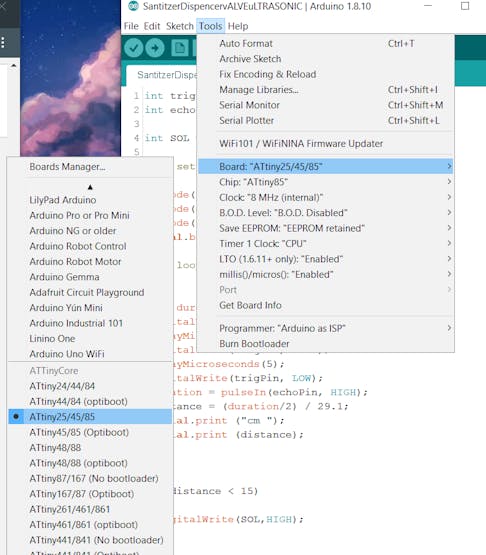
select the right MCU which is attiny85 in our case, and do not forget to choose the right com port.
STEP2
HIT BURN BOOTLOADER and wait for a few moments.
STEP3
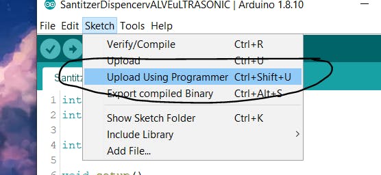
hit UPLOAD VIA Programmer
and bang, you have successfully programmed multiple tiny at the same time,
here's the result.
put them on a breadboard and connect led with D4* and GND and power them separately.
with this setup, you can program more than 1 attiny at the same time which is quite a useful feat, as you can now replicate your project at ease or you can even produce them for selling applications.
I hope this post was helpful in some way. everything here is OPENSOURCE so if you need something, just leave a comment.
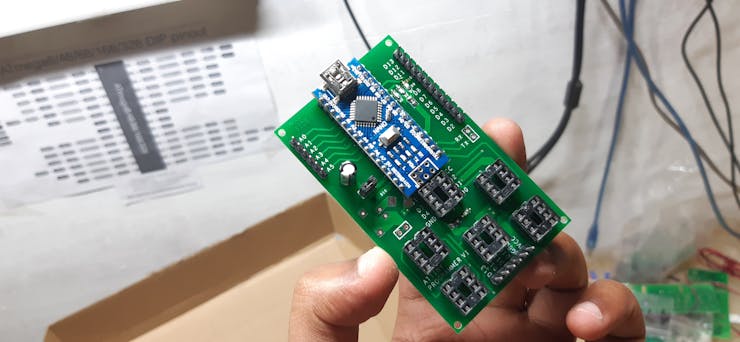
Multiple ATtiny85/13A Programmer
*PCBWay community is a sharing platform. We are not responsible for any design issues and parameter issues (board thickness, surface finish, etc.) you choose.
- Comments(1)
- Likes(3)
-
 Anthony Pedotto
Feb 22,2025
-
 Andy Rumade
Nov 26,2024
-
 EDVALDO RIBEIRO
Jul 02,2020
- 0 USER VOTES
- YOUR VOTE 0.00 0.00
- 1
- 2
- 3
- 4
- 5
- 6
- 7
- 8
- 9
- 10
- 1
- 2
- 3
- 4
- 5
- 6
- 7
- 8
- 9
- 10
- 1
- 2
- 3
- 4
- 5
- 6
- 7
- 8
- 9
- 10
- 1
- 2
- 3
- 4
- 5
- 6
- 7
- 8
- 9
- 10
 More by Arnov Arnov sharma
-
 Pocket SNES
Greetings everyone, and welcome back! Today, I’ve got something fun and tiny to share—the Pocket SNE...
-
 Batocera Arcade Box
Greetings everyone and welcome back, Here's something. Fun and nostalgic. Right now, we are using ou...
-
 64x32 Matrix Panel Setup with PICO 2
Greetings everyone and welcome back.So here's something fun and useful: a Raspberry Pi Pico 2-powere...
-
 Portable Air Quality Meter
Hello everyone, and welcome back! Today, I have something incredibly useful for you—a Portable Air Q...
-
 WALKPi PCB Version
Greetings everyone and welcome back, This is the WalkPi, a homebrew audio player that plays music fr...
-
 Delete Button XL
Greetings everyone and welcome back, and here's something fun and useful.In essence, the Delete Butt...
-
 Arduino Retro Game Controller
Greetings everyone and welcome back. Here's something fun.The Arduino Retro Game Controller was buil...
-
 Super Power Buck Converter
Greetings everyone and welcome back!Here's something powerful, The SUPER POWER BUCK CONVERTER BOARD ...
-
 Pocket Temp Meter
Greetings and welcome back.So here's something portable and useful: the Pocket TEMP Meter project.As...
-
 Pico Powered DC Fan Driver
Hello everyone and welcome back.So here's something cool: a 5V to 12V DC motor driver based around a...
-
 Mini Solar Light Project with a Twist
Greetings.This is the Cube Light, a Small and compact cube-shaped emergency solar light that boasts ...
-
 PALPi V5 Handheld Retro Game Console
Hey, Guys what's up?So this is PALPi which is a Raspberry Pi Zero W Based Handheld Retro Game Consol...
-
 DIY Thermometer with TTGO T Display and DS18B20
Greetings.So this is the DIY Thermometer made entirely from scratch using a TTGO T display board and...
-
 Motion Trigger Circuit with and without Microcontroller
GreetingsHere's a tutorial on how to use an HC-SR505 PIR Module with and without a microcontroller t...
-
 Motor Driver Board Atmega328PU and HC01
Hey, what's up folks here's something super cool and useful if you're making a basic Robot Setup, A ...
-
 Power Block
Hey Everyone what's up!So this is Power block, a DIY UPS that can be used to power a bunch of 5V Ope...
-
 Goku PCB Badge V2
Hey everyone what's up!So here's something SUPER cool, A PCB Board themed after Goku from Dragon Bal...
-
 RGB Mixinator V2
Hey Everyone how you doin!So here's a fun little project that utilizes an Arduino Nano, THE MIXINATO...
-
-
AEL-2011 Power Supply Module
513 0 2 -
AEL-2011 50W Power Amplifier
473 0 2 -
-
-
Custom Mechanical Keyboard
688 0 0 -
Tester for Touch Screen Digitizer without using microcontroller
321 2 2 -
Audio reactive glow LED wristband/bracelet with NFC / RFID-Tags
306 0 1 -
-
-


