SparkFun Cherry MX Switch Breakout
### DESCRIPTION
Cherry MX Keyswitches are top-of-the-line mechanical keyboard switches. They’re satisfyingly “clicky”, reliable up to tens-of-millions of key presses, and a standard in gaming and programming keyboards across the globe. With the SparkFun Cherry MX Switch Breakout the switches are more easily adaptable to breadboard or perfboard-based projects. The Cherry MX Switch Breakout is a perfect prototyping tool for projects ranging from a single-key user-input to fully-custom 101-key keyboards.
In addition to breaking out the switch contacts to breadboard-compatible headers, the Cherry MX Switch Breakout also provides access to an optional switch-mounted LED. Plus, the pin break-outs are designed with keyboard matrix-ing in mind, so you can interconnect as many boards as you’d like into a row-column configuration, keeping the I/O-pin requirements as low as possible.
### TECHNICAL DETAILS / COMPONENTS
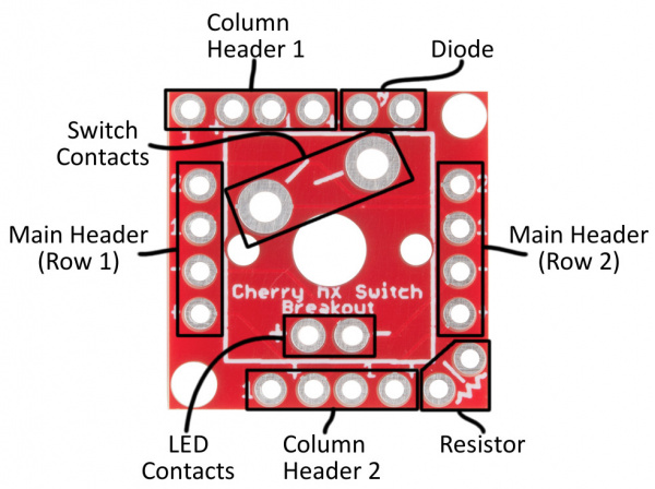
While it may seem like a simple breakout, the Cherry MX Switch Breakout board is a little over-engineered. Here’s a quick breakdown of the pin breakouts and additional features of the board.
Breakout Pin Labels
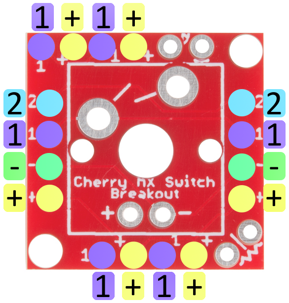
Up to four pins are used to interact with the Cherry MX Switch – two for the switch contacts and two for the optional LED. These pins are broken out on all sides of the board, labeled either “1”, “2”, “+”, or “-”. Those labels are short for:
| Pin Label | Pin Description |
|---|---|
| 1 | Switch contact 1 |
| 2 | Switch contact 2 |
| + | LED anode |
| - | LED cathode |
If you only want to use the switch, the pins labeled “1” and “2” should be all you need. If you’re integrating a 3mm LED, the LED’s anode and cathode will be accessible on the “+” and “-” pins respectively.
Header Pairs
Every side of the breakout board is equipped with a four-pin header (don’t confuse them with the diode or resistor pins), but not all of these headers are created equally! Two headers break out all four pins, while the other two headers onlybreak out the LED anode and one of the switch contacts.
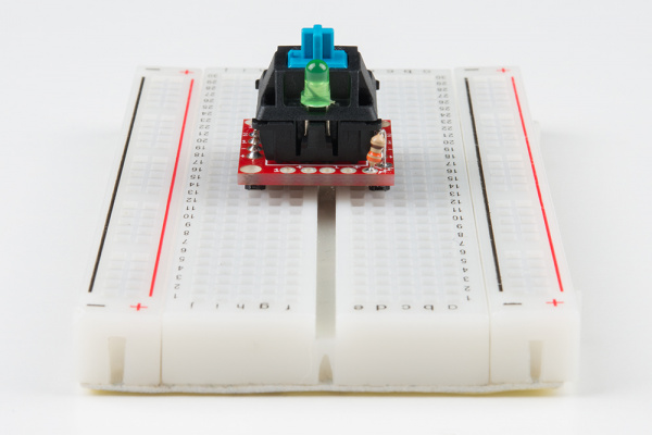
The pair of headers on the left and right sides of the board break out all four pins. These are intended for primary use. You can solder male pins into both of these headers, and plug the switch into a breadboard.
The pair of headers breaking only the LED anode and switch contact 1 are designed for keypad matrices, where multiple boards are connected in row/column pairs.
### LEARN / TOPIC / BUILD INSTRUCTIONS
Tutorial available here:
https://learn.sparkfun.com/tutorials/cherry-mx-switch-breakout-hookup-guide
SparkFun Cherry MX Switch Breakout
*PCBWay community is a sharing platform. We are not responsible for any design issues and parameter issues (board thickness, surface finish, etc.) you choose.

- Comments(0)
- Likes(7)
-
 Engineer
Dec 31,2024
-
 Mr. Marsupial
Sep 23,2023
-
 Engineer
Jul 20,2023
-
 Engineer
Oct 02,2022
-
 Jacan
Jul 14,2022
-
 Szymon Rybak
Nov 26,2020
-
 Francois BAUDRIER
Jun 30,2020
- 2 USER VOTES
- YOUR VOTE 0.00 0.00
- 1
- 2
- 3
- 4
- 5
- 6
- 7
- 8
- 9
- 10
- 1
- 2
- 3
- 4
- 5
- 6
- 7
- 8
- 9
- 10
- 1
- 2
- 3
- 4
- 5
- 6
- 7
- 8
- 9
- 10
- 1
- 2
- 3
- 4
- 5
- 6
- 7
- 8
- 9
- 10
-
10design
-
9usability
-
10creativity
-
1content
-
10design
-
10usability
-
3creativity
-
10content
 More by ?an Pevec
-
-
-
DIY Fiber Laser Tube Cutting Machine
91 0 1 -
-
-
DIY Transistor Tester | Build Your Own LCR Meter at Home with Arduino Nano
247 0 3 -
-


 Bottom Soldermask
 Top Soldermask
 Bottom Copper
 Top Silkscreen


 Top Copper
 Bottom
 Top
Top


