|
kicad 7 |
LiPo Battery Charger 3.7V
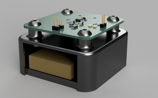
The aim of this project was to develop a customized battery charger based on the widely available TP4056 module, commonly found online. This design adapts the board to specific needs and serves as an accessible starter project for others. To ensure a tidy workspace, the charger will be integrated into a case, which will also house the battery being charged. Enjoy working on this exciting project!
Introduction
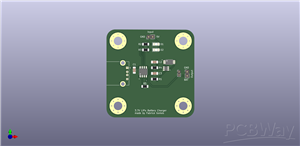
In this project, we’ll design a straightforward LiPo battery charger using the TP4056 module with integrated battery protection provided by the DW01A chip. A well-designed charging circuit is crucial to properly manage the flow of charge (electrons) into the battery. Common challenges with rechargeable batteries, such as overcharging and deep discharging, can lead to damage or reduce the battery's lifespan.
To address these challenges, the charger will incorporate intelligent features to protect the battery. It automatically halts charging when the battery reaches full capacity and disconnects power if the voltage drops below 2.4V, thereby preventing over-discharge. Additionally, the project includes a CAD file for a custom case, allowing the charger and battery to be securely housed for an organized workspace.
TP4056 Chip
The TP4056 is an integrated linear charger IC designed for single-cell lithium-ion batteries. It operates with a constant current and constant voltage, making it ideal for efficient and low-cost charging solutions.
DW01A Chip
The DW01A serves as a protection circuit for lithium-ion and lithium-polymer batteries. It safeguards against:
Overcharging: Preventing the battery voltage from exceeding safe limits (typically 4.3V–4.35V).
Deep Discharging: Cutting off power when the voltage drops below a threshold (around 2.4V–2.5V).
Short Circuits: Offering additional safety to protect both the battery and the circuit.
The DW01A is often paired with MOSFETs to enhance its protective capabilities, ensuring the battery remains safe and its lifespan is extended.
CAD Design
The custom case for this project was created in Fusion 360 and can be produced using any 3D printer. For best results, print the case horizontally to reduce the need for support structures during printing.
Tips
Replace resistor R5 with a potentiometer to enable adjustable output current, offering greater flexibility in the charging process.
Next Steps
After receiving and assembling the PCB, additional photos and updates will be included in this guide.
This project combines functionality with a clean, organized design, making it an excellent introduction to working with battery chargers. Enjoy building your customized charger and exploring its features!
LiPo Battery Charger 3.7V
*PCBWay community is a sharing platform. We are not responsible for any design issues and parameter issues (board thickness, surface finish, etc.) you choose.
- Comments(0)
- Likes(0)
- 0 USER VOTES
- YOUR VOTE 0.00 0.00
- 1
- 2
- 3
- 4
- 5
- 6
- 7
- 8
- 9
- 10
- 1
- 2
- 3
- 4
- 5
- 6
- 7
- 8
- 9
- 10
- 1
- 2
- 3
- 4
- 5
- 6
- 7
- 8
- 9
- 10
- 1
- 2
- 3
- 4
- 5
- 6
- 7
- 8
- 9
- 10
 More by Fabrice Gomes
-
-
mammoth-3D SLM Voron Toolhead – Manual Drill & Tap Edition
186 0 0 -
-
AEL-2011 Power Supply Module
713 0 2 -
AEL-2011 50W Power Amplifier
596 0 2 -
-
-
Custom Mechanical Keyboard
796 0 0 -
Tester for Touch Screen Digitizer without using microcontroller
418 2 2 -
Audio reactive glow LED wristband/bracelet with NFC / RFID-Tags
379 0 1 -
-


