


Glory to Ukraine
UKRAINE • + Follow


Description
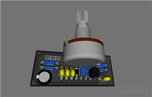
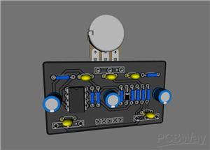
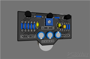
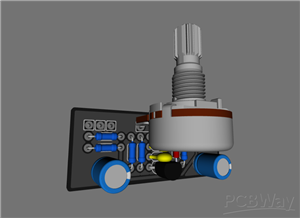
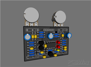
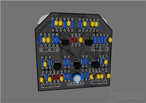
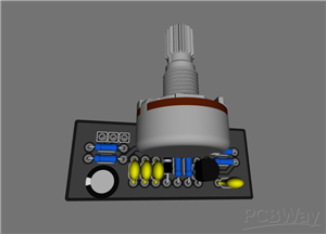
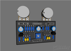
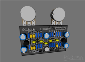
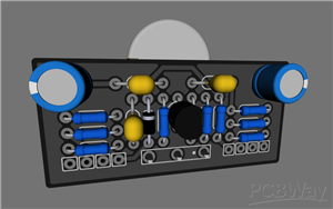
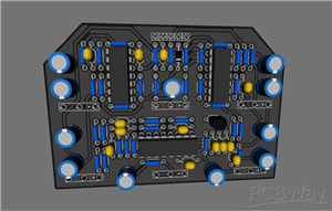
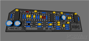
Wampler - Triple Wreck
Triple Wreck is a high gain distortion that, by its nature, is very much like some kind of metal cutting amplifier that has been proven over the years. Some will immediately recognize and decide that they are listening to some 5150. And all thanks to the sensitivity and dynamics that are more likely characteristic of a lamp head.
Schematic and Layout
Wampler_Triple_Wreck_schematic.pdf
CAD-Custom parts and enclosures
Wampler_TripleWreck.dch
Wampler_TripleWreck.dip
Wampler_TripleWrek.lay6
Jun 08,2020
12,105 views
Wampler - Triple Wreck
12105
29
18
9.80 (5)
Published: Jun 08,2020
Standard PCB
Download Gerber file 458
BOM(Bill of materials)
PCBWay Donate 10% cost To Author
File Last Updated: 2024/12/19 (GMT+8)
File update record
2024-12-1906:15:39
CAD or technical drawing file is updated.
2023-10-2620:36:24
Parts List (BOM) is updated.
Only PCB
*PCBWay community is a sharing platform. We are not responsible for any design issues and parameter issues (board thickness, surface finish, etc.) you choose.


Under the
Attribution-ShareAlike (CC BY-SA)
License.


- Comments(18)
- Likes(29)
Upload photo
You can only upload 5 files in total. Each file cannot exceed 2MB. Supports JPG, JPEG, GIF, PNG, BMP
0 / 10000
VOTING
5 votes
- 5 USER VOTES
9.80
- YOUR VOTE 0.00 0.00

-
9design
-
10usability
-
10creativity
-
10content
9.75
-
10design
-
10usability
-
10creativity
-
10content
10.00
-
10design
-
10usability
-
10creativity
-
10content
10.00
-
10design
-
10usability
-
10creativity
-
10content
10.00
-
8design
-
9usability
-
10creativity
-
10content
9.25
More by Glory to Ukraine
-
 Guitar Tone PushPull coil cut pcb
Guitar tone push pull pcb with coil cut
Guitar Tone PushPull coil cut pcb
Guitar tone push pull pcb with coil cut
-
 Wampler - Faux Analog Echo
Faux Analog Echo is a pure-sounding classic delay that preserves your natural sound without coloring...
Wampler - Faux Analog Echo
Faux Analog Echo is a pure-sounding classic delay that preserves your natural sound without coloring...
-
 Red LLama / CA Tube Sound Fuzz
The new Red Llama is a little different than the original. It is still quite impressive, but not as ...
Red LLama / CA Tube Sound Fuzz
The new Red Llama is a little different than the original. It is still quite impressive, but not as ...
-
 BearFoot - Sea Blue EQ
The BearFoot FX Sea Blue EQ provides treble and bass boost and cut in emulation of a tube-like sound...
BearFoot - Sea Blue EQ
The BearFoot FX Sea Blue EQ provides treble and bass boost and cut in emulation of a tube-like sound...
-
 ZVEX - Woolly Mammoth
The Woolly Mammoth Vexter is a fuzz pedal designed specifically for bass. Keep away from guitarists!...
ZVEX - Woolly Mammoth
The Woolly Mammoth Vexter is a fuzz pedal designed specifically for bass. Keep away from guitarists!...
-
 Wampler - Triple Wreck
Triple Wreck is a high gain distortion that, by its nature, is very much like some kind of metal cut...
Wampler - Triple Wreck
Triple Wreck is a high gain distortion that, by its nature, is very much like some kind of metal cut...
-
 EQD - Arrows (PCB 2)
EQD - Arrows (cap 5.08)
EQD - Arrows (PCB 2)
EQD - Arrows (cap 5.08)
-
 Lovepedal - Purple Plexi (PCB 2)
Lovepedal - Purple Plexi (cap 5.08)
Lovepedal - Purple Plexi (PCB 2)
Lovepedal - Purple Plexi (cap 5.08)
-
 EQD - Black Ash Fuzz
EQD - Black Ash Fuzz
EQD - Black Ash Fuzz
-
 Catalinbread - Sagrado Poblano Picoso
Catalinbread - Sagrado Poblano Picoso
Catalinbread - Sagrado Poblano Picoso
-
 BearFoot - Model G
BearFoot - Model G
BearFoot - Model G
-
 Catalinbread - Manx Loaghtan
Catalinbread - Manx Loaghtan
Catalinbread - Manx Loaghtan
-
 EQD - Arrows (pcb2)
EQD - Arrows (pcb2)
EQD - Arrows (pcb2)
-
 BearFoot - Arctic White Fuzz
BearFoot - Arctic White Fuzz
BearFoot - Arctic White Fuzz
-
 BearFoot - Emerald Green Distortion Machine
BearFoot - Emerald Green Distortion Machine
BearFoot - Emerald Green Distortion Machine
-
 BearFoot - Baby Pink Booster
BearFoot - Baby Pink Booster
BearFoot - Baby Pink Booster
-
 EQD - Sea Mashine
 chorus
EQD - Sea Mashine
EQD - Sea Mashine chorus
-
 Klon Centaur (Guitar Mania)
Klon Centaur (Guitar Mania)
Klon Centaur (Guitar Mania)
You may also like
-
-
mammoth-3D SLM Voron Toolhead – Manual Drill & Tap Edition
136 0 0 -
-
-
-
Tester for Touch Screen Digitizer without using microcontroller
392 2 2 -
Audio reactive glow LED wristband/bracelet with NFC / RFID-Tags
361 0 1 -
-


