


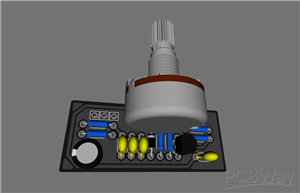
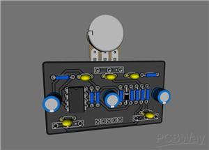
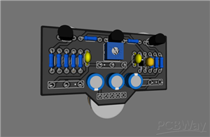
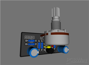
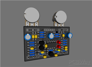
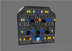
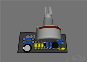
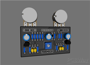
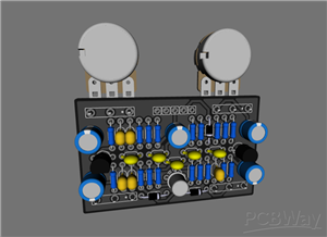
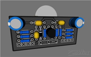
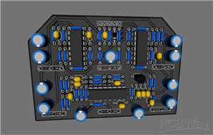
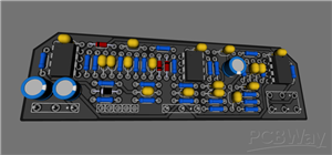
Wampler - Faux Analog Echo
Faux Analog Echo is a pure-sounding classic delay that preserves your natural sound without coloring it in any way. The Faux Analog Echo is rooted in the pedal box of numbers for musicians, from couch guitarists to global celebrities such as Brad Paisley and Brent Mason. The Faux Analog Echo is built on the popular PT2399 chip, the standard database of good delay pedals. Signal processing is based on the principle of sound integrity, as with other Wampler Pedals.
Faux Analog Echo has standard knobs Level - the level of the processed signal in the mix, Repeats - the level of feedback, Echo - the delay length (from 0 to 600 ms), as well as the Shade control, which is not typical for delays - the color of the processed signal, from warm, dense, but - as before, clean to a clear unsmoothed and sonorous tone.
Wampler - Faux Analog Echo
*PCBWay community is a sharing platform. We are not responsible for any design issues and parameter issues (board thickness, surface finish, etc.) you choose.


- Comments(15)
- Likes(13)
More by Glory to Ukraine
-
 Guitar Tone PushPull coil cut pcb
Guitar tone push pull pcb with coil cut
Guitar Tone PushPull coil cut pcb
Guitar tone push pull pcb with coil cut
-
 Wampler - Faux Analog Echo
Faux Analog Echo is a pure-sounding classic delay that preserves your natural sound without coloring...
Wampler - Faux Analog Echo
Faux Analog Echo is a pure-sounding classic delay that preserves your natural sound without coloring...
-
 Red LLama / CA Tube Sound Fuzz
The new Red Llama is a little different than the original. It is still quite impressive, but not as ...
Red LLama / CA Tube Sound Fuzz
The new Red Llama is a little different than the original. It is still quite impressive, but not as ...
-
 BearFoot - Sea Blue EQ
The BearFoot FX Sea Blue EQ provides treble and bass boost and cut in emulation of a tube-like sound...
BearFoot - Sea Blue EQ
The BearFoot FX Sea Blue EQ provides treble and bass boost and cut in emulation of a tube-like sound...
-
 ZVEX - Woolly Mammoth
The Woolly Mammoth Vexter is a fuzz pedal designed specifically for bass. Keep away from guitarists!...
ZVEX - Woolly Mammoth
The Woolly Mammoth Vexter is a fuzz pedal designed specifically for bass. Keep away from guitarists!...
-
 Wampler - Triple Wreck
Triple Wreck is a high gain distortion that, by its nature, is very much like some kind of metal cut...
Wampler - Triple Wreck
Triple Wreck is a high gain distortion that, by its nature, is very much like some kind of metal cut...
-
 EQD - Arrows (PCB 2)
EQD - Arrows (cap 5.08)
EQD - Arrows (PCB 2)
EQD - Arrows (cap 5.08)
-
 Lovepedal - Purple Plexi (PCB 2)
Lovepedal - Purple Plexi (cap 5.08)
Lovepedal - Purple Plexi (PCB 2)
Lovepedal - Purple Plexi (cap 5.08)
-
 EQD - Black Ash Fuzz
EQD - Black Ash Fuzz
EQD - Black Ash Fuzz
-
 Catalinbread - Sagrado Poblano Picoso
Catalinbread - Sagrado Poblano Picoso
Catalinbread - Sagrado Poblano Picoso
-
 BearFoot - Model G
BearFoot - Model G
BearFoot - Model G
-
 Catalinbread - Manx Loaghtan
Catalinbread - Manx Loaghtan
Catalinbread - Manx Loaghtan
-
 EQD - Arrows (pcb2)
EQD - Arrows (pcb2)
EQD - Arrows (pcb2)
-
 BearFoot - Arctic White Fuzz
BearFoot - Arctic White Fuzz
BearFoot - Arctic White Fuzz
-
 BearFoot - Emerald Green Distortion Machine
BearFoot - Emerald Green Distortion Machine
BearFoot - Emerald Green Distortion Machine
-
 BearFoot - Baby Pink Booster
BearFoot - Baby Pink Booster
BearFoot - Baby Pink Booster
-
 EQD - Sea Mashine
 chorus
EQD - Sea Mashine
EQD - Sea Mashine chorus
-
 Klon Centaur (Guitar Mania)
Klon Centaur (Guitar Mania)
Klon Centaur (Guitar Mania)
-
-
-
-
Tester for Touch Screen Digitizer without using microcontroller
340 2 2 -
Audio reactive glow LED wristband/bracelet with NFC / RFID-Tags
322 0 1 -
-
-


