


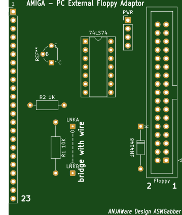


Amiga External Floppy PC drive interface(repaired)
A long time ago in city not far from here I was a kid in a shop called microbyte, looking for games for my amiga a500, I had just got the 1 meg upgrade that I had saved up for when the sales assistant put jesus on e's (https://youtu.be/x37gIahAtXQ) on the shop amiga and cranked the speakers up, after my jaw dropped in amazement, i asked what is was and where to get, the assistant replied "its p.d so buy 2 disks and I'll copy you it". As I rushed home I was more excited about the P.d demo discs that I had just gotten rather than the game which i had bought. As soon as i arrived home i put my amiga on put disk 1 of jesus on e's in my amiga, it was at this point i found out to play the demo you needed a secondary floppy drive (which I never had) so I started saving again, but for whatever reasons I never got the ext floppy drive fast forward a few decades i get my old amiga out of the loft, I dust it off, sort it out so its in running order. As soon as i discovered the disks I had to have an external floppy drive, I just wanted that demo to work on my amiga. After seeing how much external amiga drives cost on ebay (which is just as much as an amiga itself costs to buy practically), I thought about building my own and with a bit of help from the amiga guru book and my 11 year old daughter with some investigating on the internet, we (myself and my daughter) built a prototype drive interface which did not work! but the drive light lit up, the drive made the right noises just something was not quite right. After about 8 different revisions, we arrived at a working prototype (shown in pictures) and the attached gerbers are the designs that we come up with from that, we hope to eventually use these in our home made External Drive. I finally got to see the demo run on my amiga, which is still as impressive and amazing as it was in 199, but more importantly I had a great time working with my daughter.
(**** 23 pin male D connectors are getting rare and harder to get, you can recycle an old serial 25 Pin D plug by sawing/rotary tooling off the end 2 pins at the angle they form, trim off the knub left over and with a little sanding and tweaking you can make the plug fit your amiga and use as normal, same thing applies for a video cables with a old printer cable.)

Amiga External Floppy PC drive interface(repaired)
*PCBWay community is a sharing platform. We are not responsible for any design issues and parameter issues (board thickness, surface finish, etc.) you choose.


Raspberry Pi 5 7 Inch Touch Screen IPS 1024x600 HD LCD HDMI-compatible Display for RPI 4B 3B+ OPI 5 AIDA64 PC Secondary Screen(Without Speaker)
BUY NOW
ESP32-S3 4.3inch Capacitive Touch Display Development Board, 800×480, 5-point Touch, 32-bit LX7 Dual-core Processor
BUY NOW
Raspberry Pi 5 7 Inch Touch Screen IPS 1024x600 HD LCD HDMI-compatible Display for RPI 4B 3B+ OPI 5 AIDA64 PC Secondary Screen(Without Speaker)
BUY NOW


- Comments(18)
- Likes(16)
 More by asmgabber
-
Commodore 64 1541-II 1581 Floppy Disk Drive C64 Power Supply Unit USB-C 5V 12V DIN connector 5.25
164 1 3 -
Easy to print simple stacking organizer with drawers
87 0 0 -
-
-
Modifying a Hotplate to a Reflow Solder Station
1137 1 6 -
MPL3115A2 Barometric Pressure, Altitude, and Temperature Sensor
638 0 1 -
-
-
V2 Commodore AMIGA USB-C Power Sink Delivery High Efficiency Supply Triple Output 5V ±12V OLED display ATARI compatible shark 100W
1439 4 3


look at adding a transistor as a switch to a led on pin 2 of the 74hc74 it will illuminate when the disk is spinning
I think also pin 17 of the floppy cable is write data doing the same with a transistor on that pin should probably work, wonder if read data (pin2) would be a better option for a read led also
Reason why I ask it is because 720kb drives are almost impossible to find. Btw. 1.44Mb drives are also getting harder to find, but that is because everyone is binning them ;)
it does work with a 1.44mb drive but if you use a high density disk you will have to cover the extra hole or cut the pin off on the inside of the drive
im using mine with a nec fd1231h https://www.cnet.com/products/nec-fd1231h-floppy-disk-drive-floppy-series/
Thank you for your answer!
I can repair floppy disc drives. I use the industry standard equipment and can repair test and reset alignment. Regards Mark 01666 824031 uk
Hi please thanks for the update I have updated the gerebers and please see attached image on how to fix the issue
Thanks, I made the fixes and it works.
Sorted :)
Hi im new to kicad if you have any idea how to export the missing bits i can update
I think that's it if you wouldn't mind checking, i completed the outline on the wrong layer so it wasn't seeing it as a cut out :)