


Catia Diaz
MEXICO • + Follow

Components

|
TB004-508-02BESame Sky (Formerly CUI Devices)
|
x 5 | |
|
|
ESP32-C3 SUPER MINI V2Maker go
|
x 1 |
Tools, APP Software Used etc.

|
Soldering Iron Kit |
|

|
Solder Wire, Lead Free |
|

|
Smart Soldering Iron TS101-BC2 |
Description
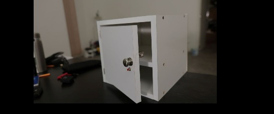
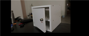
CIRCUIT WITH ESP32 C3 TO CONTROL ELECTRIC LOCK
I will apply this circuit to build a safe to store the phone and thus not use it for a long time and get rid of my addiction to it.
Lista de materiales completa:
2 Capacitores SMD 1206 100nF
5 Borneras 3.5 mm de 2 terminales
1 Buzzer SMD 9650
2 Resistencias SMD 1206 10K
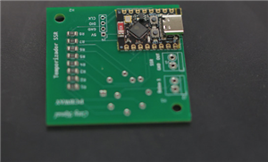
1 ESP 32 C3 SUPERMINI
1 Regulador de voltaje AMS 1117 SOT89
1 Puenrte H L9110S
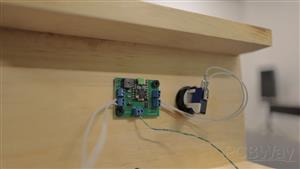
See more details about the plate and the project that uses this lock in the following tutorial
Code
programming code
Arduino
// Definición de pines const int botonPin = 3; // Pin de entrada para el botón (GPIO 3) const int cerraduraPin = 4; // Pin de salida para la cerradura (GPIO 4) const int buzzerPin = 6; // Pin de salida para el buzzer (GPIO 6) // Variables para millis() unsigned long tiempoInicio = 0; bool enSecuencia = false; int pasoSecuencia = 0; void setup() { pinMode(botonPin, INPUT_PULLUP); pinMode(cerraduraPin, OUTPUT); pinMode(buzzerPin, OUTPUT); digitalWrite(cerraduraPin, LOW); // Cerradura inicialmente desbloqueada digitalWrite(buzzerPin, LOW); // Buzzer apagado } void loop() { int estadoBoton = digitalRead(botonPin); // Iniciar secuencia con primera pulsación if (!enSecuencia && estadoBoton == LOW) { enSecuencia = true; tiempoInicio = millis(); pasoSecuencia = 1; digitalWrite(buzzerPin, HIGH); // Paso 1: Pitido 0.5s } if (enSecuencia) { unsigned long tiempoActual = millis(); switch (pasoSecuencia) { case 1: // Buzzer 0.5s if (tiempoActual - tiempoInicio >= 500) { digitalWrite(buzzerPin, LOW); digitalWrite(cerraduraPin, HIGH); // Paso 2: Activar cerradura 1s tiempoInicio = tiempoActual; pasoSecuencia = 2; } break; case 2: // Cerradura 1s if (tiempoActual - tiempoInicio >= 1000) { digitalWrite(cerraduraPin, LOW); tiempoInicio = tiempoActual; pasoSecuencia = 3; // Paso 3: Esperar 8s } break; case 3: // Espera 8s if (tiempoActual - tiempoInicio >= 8000) { digitalWrite(buzzerPin, HIGH); // Paso 4: Buzzer 3s tiempoInicio = tiempoActual; pasoSecuencia = 4; } break; case 4: // Buzzer 3s if (tiempoActual - tiempoInicio >= 3000) { digitalWrite(buzzerPin, LOW); pasoSecuencia = 5; // Paso 5: Esperar segunda pulsación } break; case 5: // Esperar segunda pulsación if (estadoBoton == LOW) { digitalWrite(cerraduraPin, HIGH); // Paso 6: Activar cerradura 5s tiempoInicio = tiempoActual; pasoSecuencia = 6; } break; case 6: // Cerradura 5s if (tiempoActual - tiempoInicio >= 5000) { digitalWrite(cerraduraPin, LOW); enSecuencia = false; // Reiniciar sistema } break; } } }
programming code
mueble_activa_cerrojo_electronico.ino
Arduino
// Definición de pines const int botonPin = 3; // Pin de entrada para el botón (GPIO 3) const int cerraduraPin = 4; // Pin de salida para la cerradura (GPIO 4) const int buzzerPin = 6; // Pin de salida para el buzzer (GPIO 6) // Variables para millis() unsigned long tiempoInicio = 0; bool enSecuencia = false; int pasoSecuencia = 0; void setup() { pinMode(botonPin, INPUT_PULLUP); pinMode(cerraduraPin, OUTPUT); pinMode(buzzerPin, OUTPUT); digitalWrite(cerraduraPin, LOW); // Cerradura inicialmente desbloqueada digitalWrite(buzzerPin, LOW); // Buzzer apagado } void loop() { int estadoBoton = digitalRead(botonPin); // Iniciar secuencia con primera pulsación if (!enSecuencia && estadoBoton == LOW) { enSecuencia = true; tiempoInicio = millis(); pasoSecuencia = 1; digitalWrite(buzzerPin, HIGH); // Paso 1: Pitido 0.5s } if (enSecuencia) { unsigned long tiempoActual = millis(); switch (pasoSecuencia) { case 1: // Buzzer 0.5s if (tiempoActual - tiempoInicio >= 500) { digitalWrite(buzzerPin, LOW); digitalWrite(cerraduraPin, HIGH); // Paso 2: Activar cerradura 1s tiempoInicio = tiempoActual; pasoSecuencia = 2; } break; case 2: // Cerradura 1s if (tiempoActual - tiempoInicio >= 1000) { digitalWrite(cerraduraPin, LOW); tiempoInicio = tiempoActual; pasoSecuencia = 3; // Paso 3: Esperar 8s } break; case 3: // Espera 8s if (tiempoActual - tiempoInicio >= 8000) { digitalWrite(buzzerPin, HIGH); // Paso 4: Buzzer 3s tiempoInicio = tiempoActual; pasoSecuencia = 4; } break; case 4: // Buzzer 3s if (tiempoActual - tiempoInicio >= 3000) { digitalWrite(buzzerPin, LOW); pasoSecuencia = 5; // Paso 5: Esperar segunda pulsación } break; case 5: // Esperar segunda pulsación if (estadoBoton == LOW) { digitalWrite(cerraduraPin, HIGH); // Paso 6: Activar cerradura 5s tiempoInicio = tiempoActual; pasoSecuencia = 6; } break; case 6: // Cerradura 5s if (tiempoActual - tiempoInicio >= 5000) { digitalWrite(cerraduraPin, LOW); enSecuencia = false; // Reiniciar sistema } break; } } }
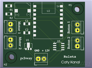
Schematic and Layout
Diagram
Diagrama ruleta.png

Feb 25,2025
195 views
end-flag
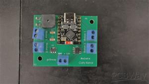
CIRCUIT WITH ESP32 C3 TO CONTROL ELECTRIC LOCK
2 Layers PCB 40 x 50 mm FR-4, 1.6 mm, 1, HASL lead free, Green Solder Mask, White silkscreen
With the help of this circuit you can control a 12V 500mA electric lock
We will use programming in the Arduino IDE
195
0
0
Published: Feb 25,2025
Download Gerber file 0
BOM(Bill of materials)
PCBWay Donate 10% cost To Author
File Last Updated: 2025/02/25 (GMT+8)
File update record
2025-02-2509:03:43
Parts List (BOM) is updated.
Only PCB
PCB+Assembly
*PCBWay community is a sharing platform. We are not responsible for any design issues and parameter issues (board thickness, surface finish, etc.) you choose.


Under the
Attribution-ShareAlike (CC BY-SA)
License.


Raspberry Pi 5 7 Inch Touch Screen IPS 1024x600 HD LCD HDMI-compatible Display for RPI 4B 3B+ OPI 5 AIDA64 PC Secondary Screen(Without Speaker)
BUY NOW
ESP32-S3 4.3inch Capacitive Touch Display Development Board, 800×480, 5-point Touch, 32-bit LX7 Dual-core Processor
BUY NOW
Raspberry Pi 5 7 Inch Touch Screen IPS 1024x600 HD LCD HDMI-compatible Display for RPI 4B 3B+ OPI 5 AIDA64 PC Secondary Screen(Without Speaker)
BUY NOW


- Comments(0)
- Likes(0)
 Log in to post comments.
Upload photo
0 / 10000
More by Catia Diaz
-
 PCB for charging AA rechargeable batteries
With this card you can charge from 1 to 5 AA batteries independently. With the charger you can selec...
PCB for charging AA rechargeable batteries
With this card you can charge from 1 to 5 AA batteries independently. With the charger you can selec...
-
 H bridge module to control crank
With the help of this H-bridge circuit we can control the rotation of a motor, and better yet, if we...
H bridge module to control crank
With the help of this H-bridge circuit we can control the rotation of a motor, and better yet, if we...
-
 Design to control 7 segment display with switches
One way to connect a 7-segment display is using cables and switches.In order to form a number you wi...
Design to control 7 segment display with switches
One way to connect a 7-segment display is using cables and switches.In order to form a number you wi...
-
 Wireless control for motor dc
It is a pair of PCBs that allow transmitting a signal that is sent through 4 buttons and received by...
Wireless control for motor dc
It is a pair of PCBs that allow transmitting a signal that is sent through 4 buttons and received by...
-
 Led lamp replacement
This is a replacement for lamps commonly used in the ceiling.These lamps, being cheap, break down ea...
Led lamp replacement
This is a replacement for lamps commonly used in the ceiling.These lamps, being cheap, break down ea...
-
 2835 SMD led strip for students
One application that I gave to this circular LED strip is to illuminate a beverage counter.Use only ...
2835 SMD led strip for students
One application that I gave to this circular LED strip is to illuminate a beverage counter.Use only ...
-
 Led strip 5630 SMD with screw terminal
This project is designed for 2 things. The first is so that people can practice soldering SMD compon...
Led strip 5630 SMD with screw terminal
This project is designed for 2 things. The first is so that people can practice soldering SMD compon...
-
 Bluetooth control for LED lights or motors with ESP32 C3
Con esta tarjeta puedes controlar vía Bluetooth motores o luces led con ayuda del ESP32 C3 (yo utili...
Bluetooth control for LED lights or motors with ESP32 C3
Con esta tarjeta puedes controlar vía Bluetooth motores o luces led con ayuda del ESP32 C3 (yo utili...
-
 Control de luces led con servidor web y ESP32 C3
Te comparto todos los archivos que necesitas para realizar esta practica, encontraras 2 códigos de p...
Control de luces led con servidor web y ESP32 C3
Te comparto todos los archivos que necesitas para realizar esta practica, encontraras 2 códigos de p...
-
 CIRCUIT WITH ESP32 C3 TO CONTROL ELECTRIC LOCK
I will apply this circuit to build a safe to store the phone and thus not use it for a long time and...
CIRCUIT WITH ESP32 C3 TO CONTROL ELECTRIC LOCK
I will apply this circuit to build a safe to store the phone and thus not use it for a long time and...
-
 Tarjeta para controlar un motor para Ruleta con ESP32 C3 Super Mini
Lista de materiales completa:2 Capacitores SMD 1206 100nF5 Borneras 3.5 mm de 2 terminales1 Buzzer S...
Tarjeta para controlar un motor para Ruleta con ESP32 C3 Super Mini
Lista de materiales completa:2 Capacitores SMD 1206 100nF5 Borneras 3.5 mm de 2 terminales1 Buzzer S...
-
 Tira led circular 2835 de 12V
Lista de materiales para la PCB:6 Leds 2835 (naranja)2 Resistencias 1206 100 Ohms1 Bornera 2 tornill...
Tira led circular 2835 de 12V
Lista de materiales para la PCB:6 Leds 2835 (naranja)2 Resistencias 1206 100 Ohms1 Bornera 2 tornill...
-
 Números aleatorios para dinámicas divertidas de participación
Lista de materiales completa:5 Borneras de 2 terminales cada una2 Cap 100n (SMD 1206)2 Resistencias ...
Números aleatorios para dinámicas divertidas de participación
Lista de materiales completa:5 Borneras de 2 terminales cada una2 Cap 100n (SMD 1206)2 Resistencias ...
-
 Numeros aleatorios matriz-
Se trata de una PCB con esp32 que permite controlar una matriz de leds ws2812bLista de materiales co...
Numeros aleatorios matriz-
Se trata de una PCB con esp32 que permite controlar una matriz de leds ws2812bLista de materiales co...
-
 Esp 32 wireless communication card
Here you can see more details of the programming process
Esp 32 wireless communication card
Here you can see more details of the programming process
-
 Card for LED light sequence and memory game
Here you can find the complete tutorial to see how this game works.Characteristics of the assembly o...
Card for LED light sequence and memory game
Here you can find the complete tutorial to see how this game works.Characteristics of the assembly o...
-
 Timer with 5-position selector and ESP 32 C3 super mini
Full tutorial in the following video
Timer with 5-position selector and ESP 32 C3 super mini
Full tutorial in the following video
-
 USB Charger
Its a charger with a 7 segments display to stop with the time the charge, its controlled with a esp3...
USB Charger
Its a charger with a 7 segments display to stop with the time the charge, its controlled with a esp3...
-
PCB for charging AA rechargeable batteries
With this card you can charge from 1 to 5 AA batteries independently. With the charger you can selec...
-
H bridge module to control crank
With the help of this H-bridge circuit we can control the rotation of a motor, and better yet, if we...
-
Design to control 7 segment display with switches
One way to connect a 7-segment display is using cables and switches.In order to form a number you wi...
-
Wireless control for motor dc
It is a pair of PCBs that allow transmitting a signal that is sent through 4 buttons and received by...
-
Led lamp replacement
This is a replacement for lamps commonly used in the ceiling.These lamps, being cheap, break down ea...
-
2835 SMD led strip for students
One application that I gave to this circular LED strip is to illuminate a beverage counter.Use only ...
-
Led strip 5630 SMD with screw terminal
This project is designed for 2 things. The first is so that people can practice soldering SMD compon...
-
Bluetooth control for LED lights or motors with ESP32 C3
Con esta tarjeta puedes controlar vía Bluetooth motores o luces led con ayuda del ESP32 C3 (yo utili...
-
Control de luces led con servidor web y ESP32 C3
Te comparto todos los archivos que necesitas para realizar esta practica, encontraras 2 códigos de p...
-
CIRCUIT WITH ESP32 C3 TO CONTROL ELECTRIC LOCK
I will apply this circuit to build a safe to store the phone and thus not use it for a long time and...
-
Tarjeta para controlar un motor para Ruleta con ESP32 C3 Super Mini
Lista de materiales completa:2 Capacitores SMD 1206 100nF5 Borneras 3.5 mm de 2 terminales1 Buzzer S...
-
Tira led circular 2835 de 12V
Lista de materiales para la PCB:6 Leds 2835 (naranja)2 Resistencias 1206 100 Ohms1 Bornera 2 tornill...
You may also like
-
-
Commodore 64 1541-II 1581 Floppy Disk Drive C64 Power Supply Unit USB-C 5V 12V DIN connector 5.25
215 1 3 -
Easy to print simple stacking organizer with drawers
96 0 0 -
-
-
-
-
-
Modifying a Hotplate to a Reflow Solder Station
1176 1 6 -
MPL3115A2 Barometric Pressure, Altitude, and Temperature Sensor
660 0 1 -


