DIY a Smart NiMH/NiCd Battery Charger
When talking about standalone single cell battery chargers only one popular name came into my mind that is our versatile Li-Ion/Li-Po TP4056 battery charger. Which is vastly available and has a lot of features related to battery protection. But what about the other batteries which work on a lower potential, for example the crude NiMh or NiCd (Nickel metal hydride or nickel cadmium). There are a lot of DIY options available, but because these batteries work at lower voltage (1.2V) there is not a specific and standard method to charge.
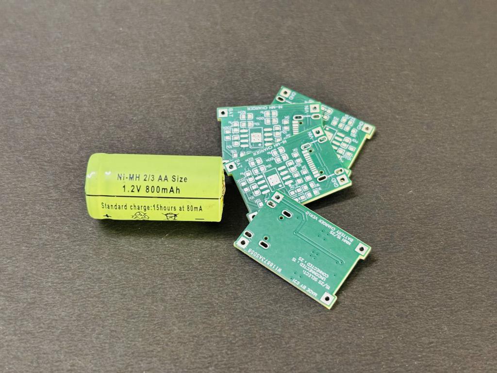
One simple method is to create a constant current power supply, and charge the batteries at 1/10C rating for 10-16 Hours, this method is used in low cost applications. But the standard method to charge the batteries with all the battery protection features can be an integrated circuit like TP4056.
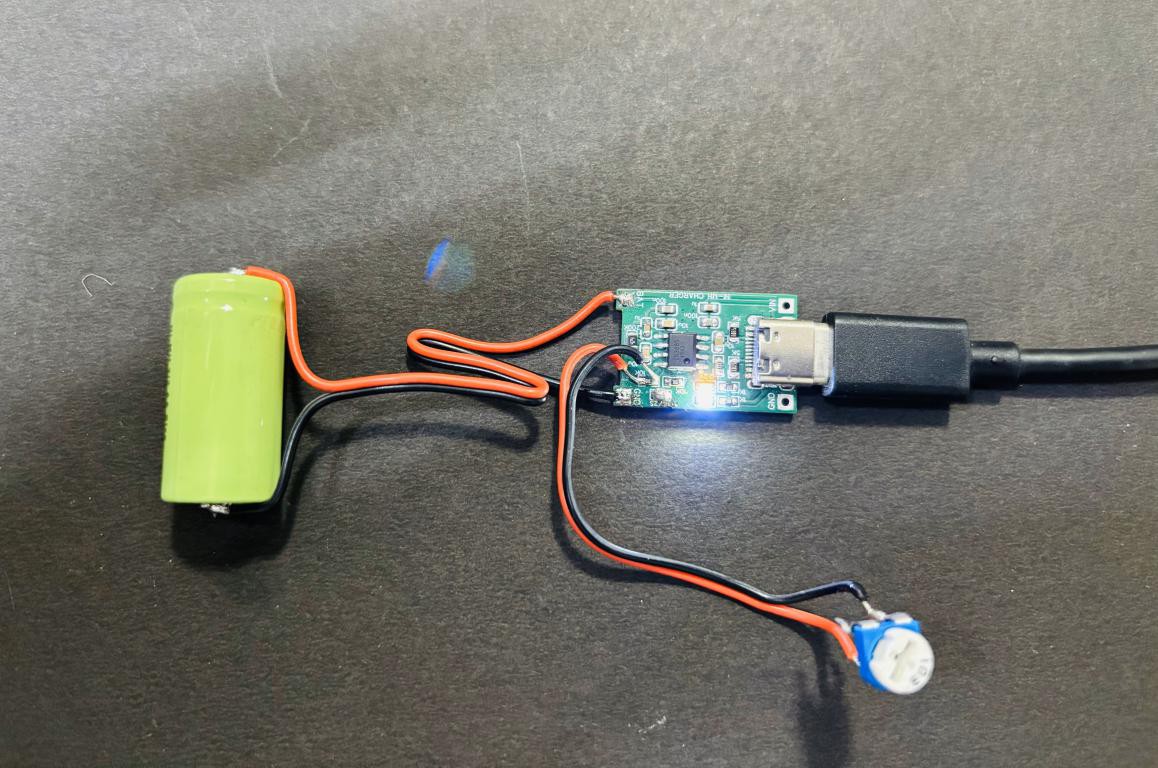
Luckily I found the one solution after searching the web a lot which works the same, it is CN3085 NiMH single to three cell battery charger IC. The device contains an on-chip power MOSFET and eliminates the need for the external sense resistor and blocking diode. CN3085 requires few external components, and is suitable for portable applications. Like TP4056 Li-ion, the charge current can be set externally with a single resistor. Other features include undervoltage lockout, automatic recharge, the constant current charging, the maintenance charge mode(timer termination), charge/termination indicators and battery temperature monitoring. All the modes and battery charging process is given below with all details. Big thanks to PCBWay for sponsoring the PCBs for this project! Their high-quality manufacturing and quick turnaround made this build possible.
Features:
- On-chip Power MOSFET
- Voltage accuracy:1>#/span###
- Precharge Conditioning for reviving deeply discharged cells
- Charge Current up to 1A
- Constant-Current/Constant-Temperature operation with thermal regulation
- Automatic Low-Power Sleep Mode when input supply voltage is removed
- Indicators for Charge and termination status
- Maintenance Charge Mode(Timer Termination)
- Automatic Recharge
- Battery Temperature Monitoring
Circuit diagram:
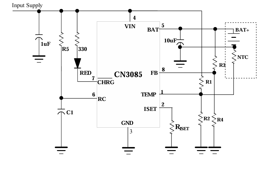
Here is the typical application circuit as per the datasheet of the IC, the circuit can be modified according to the needs from 1 cell to 3 cell battery charge applications. I am designing the battery charger for 1S/2S cells. The resistor divider on the output, works as a feedback system which keeps the voltage in the range of 1.2V and sets the output voltage. Battery voltage is fed back to the CN3085 through this pin. The CN3085 determines the charge mode based on the FB pin voltage. The battery terminal voltage at BAT pin is given by : VBAT=VFB×(1+R3/R4) .

Moreover we need a potentiometer to adjust the output voltage as per the cell rating. The changing voltage may go up to 1.3-1.35V in this case. The potentiometer can be removed and replaced with a fixed resistor after that which eliminates its need. Or we can use a divider network as shown in the modified circuit diagram below. I eliminated the battery temperature monitoring function for now, because for that we need a NTC which is placed very near to the battery surface which is not possible with this unit.
PCB and Gerber file:
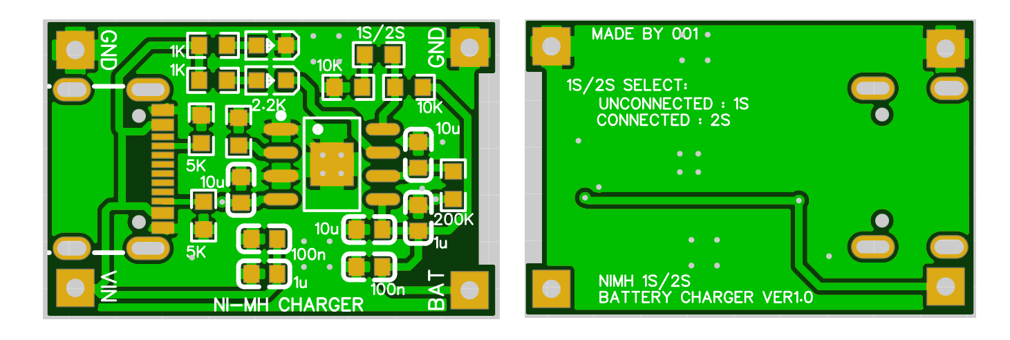
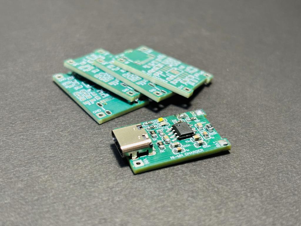
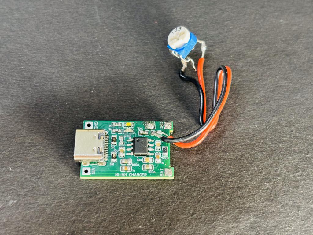
To keep the circuit simple and in low form factor, I took my motivation from the TP4056 again and designed the PCB as per that. The PCB has an input charging 5V type C port, some led indicators which monitor battery charging state and turn on/off according to whether the battery is full or not. If the charging mode is on, the indicator LED remains on otherwise off. Some power supply decoupling capacitor and a feedback loop makes this board fully compatible to charge a 1S/2S battery. The cell voltage can be changed from 1S to 2S from the onboard jumper. Otherwise a variable resistor can be used to tune the output voltage.
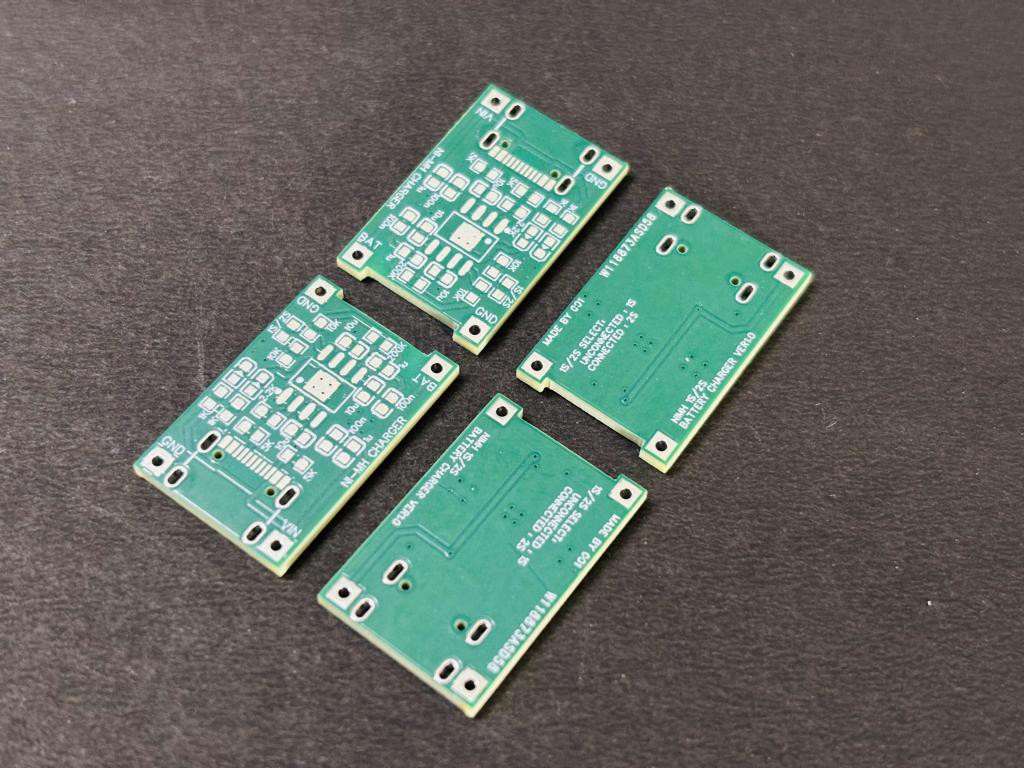
As I got my hands on the PCBs from PCBWAY, I soldered all the components. And tested out all the modes given below. Sign-up now using this link and get free coupons to order your first PCB. All the required files Geber, BOM, pick and place are uploaded on the PCBhub see from here.
Battery Charging process and modes:
Precharge mode: If FB pin voltage falls below 0.843V, or we can say the battery voltage is below 70% of the maximum voltage of the battery terminal, the CN3085 goes into precharge mode, and the charge current is regulated at 10% of that in constant current charge mode.
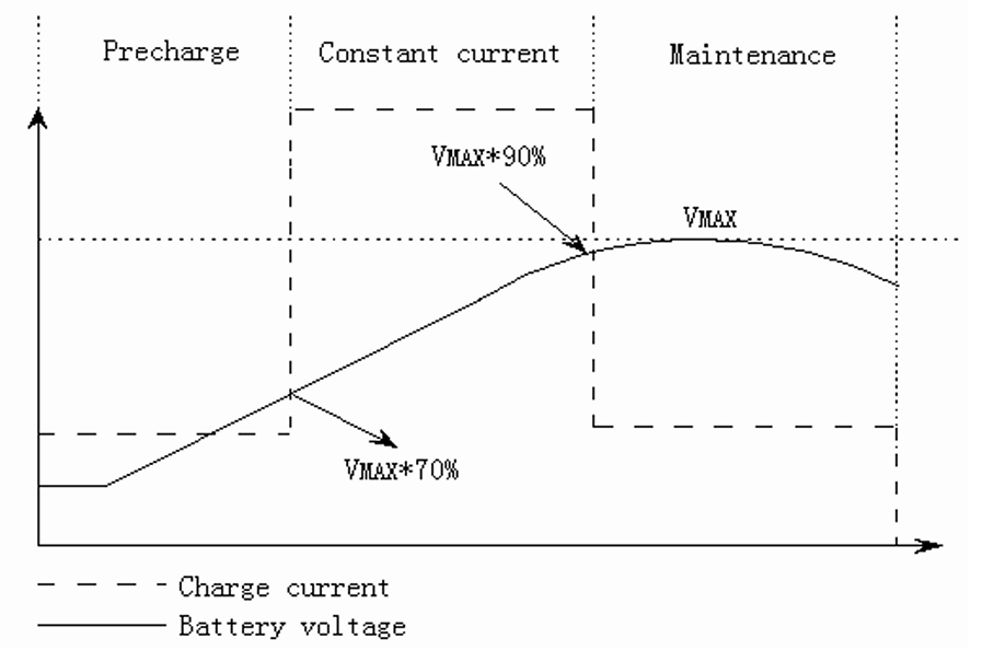
Constant Current charge mode: If FB pin voltage is greater than 0.843V, and less than 1.083V, the CN3085 is in constant current charge mode. In the constant current charge mode, the charge current is determined by the following equation as per datasheet circuit: ICH = 1218V / RISET.
For example, if 1A charge current is needed: RISET = 1218V/1A = 1.218kΩ For the stability over temperature and time, metal film resistance with 1% accuracy is recommended.
Once the voltage at FB pin rises above 1.083V, the CN3085 stops the constant current charge and enters into the maintenance charge mode, at this time the corresponding voltage at BAT pin is determined by the following equation: VBAT = 1.205 × 90% × (1 + R3/R4).
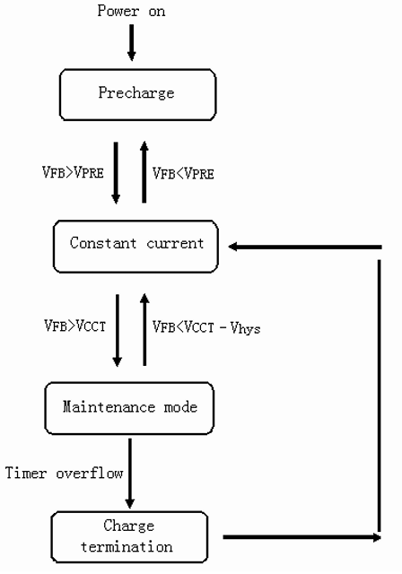
Maintenance Charge Mode: If the voltage at FB pin rises above 1.083V(90% of FB maximum voltage), the constant current charge mode is stopped, and the CN3085 goes into the maintenance charge mode. The charge current in maintenance mode is 60% of the constant charge current. An internal timer is started once the CN3085 is in the maintenance charge mode, this puts a time limit on the maintenance charge mode, the time limit is programmed by a resistor and a capacitor at the RC pin. After the timeout occurs, the whole charge cycle is terminated, the CN3085 enters into termination mode. In maintenance charge mode, the time limit is determined by the following equation: T=2654×R5×C1+4980×C1×103 Where: T is the time limit in second R5 is the resistor from RC pin to VIN pin, the unit is ohm, R5 should range from 20kΩ to 5MΩ, otherwise, the timer’s accuracy may be affected. C1 is the capacitor from RC pin to GND, the unit is Farad, C1 should be greater than 1nF, otherwise, the timer’s accuracy may be affected.
Charge Termination in NiCd/NiMh batteries:
The –∆V (negative delta V) fast charge termination is a method used to detect when a nickel-metal hydride (NiMH) battery is fully charged and to stop the charging process to prevent overcharging. This technique is based on monitoring the battery voltage during the charging cycle.
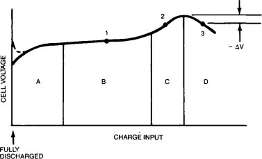
During the charging of NiMH batteries, the voltage rises steadily until the battery is nearly full. Once the battery reaches full capacity, a slight drop in voltage occurs, which is referred to as a "negative delta voltage." This voltage drop happens due to internal electrochemical changes as the battery is fully charged, causing a temporary decrease in terminal voltage.
To implement the –∆V termination, the charging circuit continuously measures the voltage of the battery pack. When it detects a decrease in voltage (the "negative delta"), it recognizes that the battery is fully charged and stops the charging process or switches to a trickle charge mode.
Key points about –∆V fast charge termination:
1. Prevents Overcharging: Stops charging at the right point, which helps protect the battery and prolong its lifespan.
2. Accurate Detection: The slight voltage drop can be subtle, so precision in monitoring is necessary.
3. Temperature Correlation: Fully charged NiMH cells generate heat, so some chargers also use temperature sensing as a secondary indicator.
However, one downside of –∆V termination is that it may not work well if the charging current is too low, as the voltage change can be difficult to detect in such conditions.
Working:
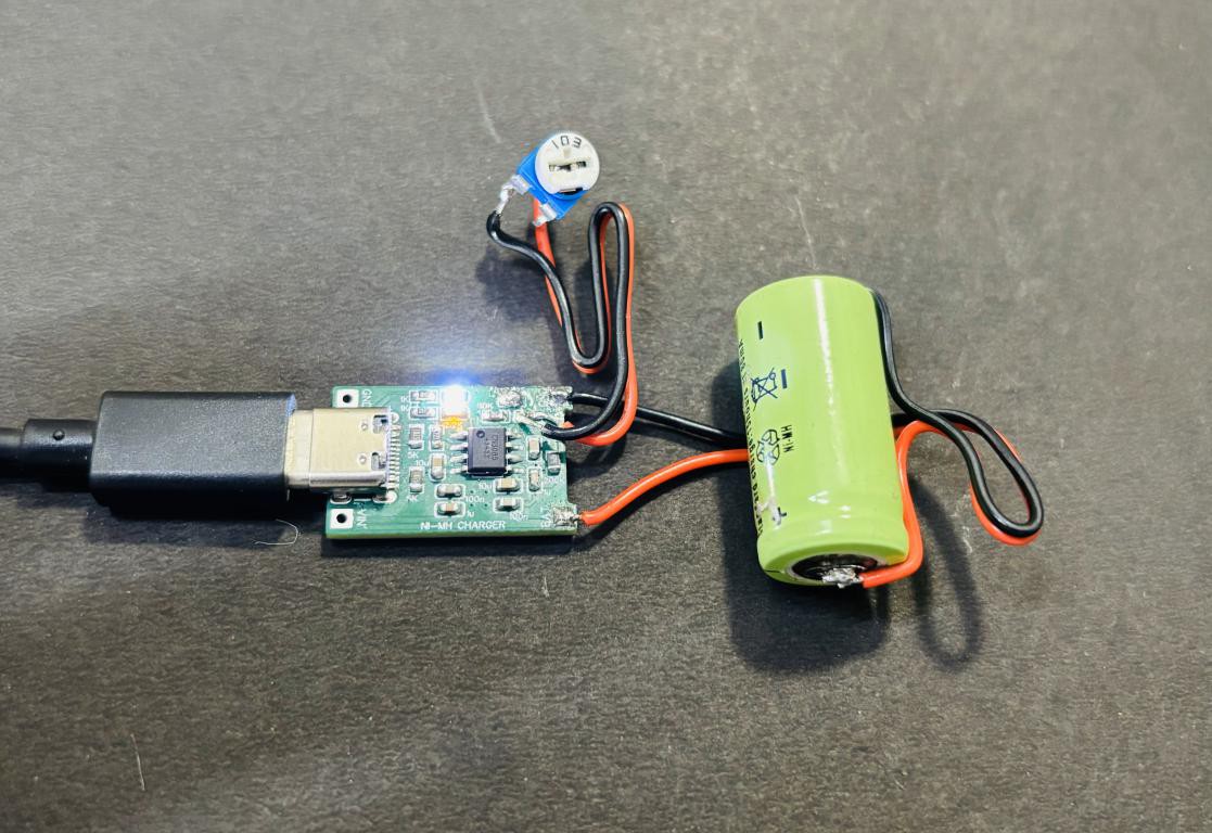
A huge part of this project’s success is thanks to PCBWay’s top-notch PCB manufacturing. Fast, efficient, and always on point! The PCB is very clean and specific because all the battery protection features, charging modes selections and automatically done by the IC itself. I have tested all the modes by charging a 1.2V 800mAH NiMH battery, which recommends a charging current of 80mA for 16 hours but with this charger it is possible to fully charge the battery in just 3 hours from a deeply discharged state. I will recommend using this charger, all the files are uploaded on the PCBWAY hub check them out from here
DIY a Smart NiMH/NiCd Battery Charger
*PCBWay community is a sharing platform. We are not responsible for any design issues and parameter issues (board thickness, surface finish, etc.) you choose.
- Comments(0)
- Likes(2)
-
 XIANG LIU
May 23,2025
-
 Green Pimienta
Nov 30,2024
- 0 USER VOTES
- YOUR VOTE 0.00 0.00
- 1
- 2
- 3
- 4
- 5
- 6
- 7
- 8
- 9
- 10
- 1
- 2
- 3
- 4
- 5
- 6
- 7
- 8
- 9
- 10
- 1
- 2
- 3
- 4
- 5
- 6
- 7
- 8
- 9
- 10
- 1
- 2
- 3
- 4
- 5
- 6
- 7
- 8
- 9
- 10
 More by Engineer
-
 DIY a Smart NiMH/NiCd Battery Charger
When talking about standalone single cell battery chargers only one popular name came into my mind t...
-
 LiFePO4 Battery Charger With Protection
In the previous few months I tried to cover almost all types of battery charging integrated circuits...
-
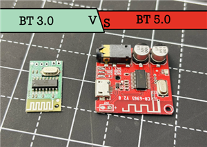 Comparison of Audio Bluetooth 3.0 and 5.0
Coming to bluetooth in audio applications, we have versions from 3.0 to 5.4. In the practical audio ...
-
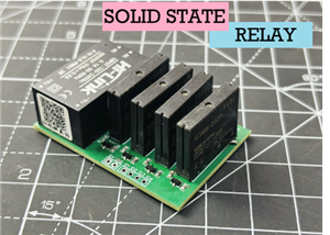 4 Channel SOLID STATE RELAY Module
I have designed a triac and optocoupler based project in the past, in which triac act as a relay and...
-
 A Look at Capacitive Water Overflow Sensor
Detection of Water overflow in a tank is one of the main topics when it comes to energy saving appli...
-
 Offline Voice Recognition Hub Based on ESPNOW
An offline voice recognition hub, no internet connection, no wifi router. Just a pair of ESP8266 wit...
-
 DIY a 200W Precise Electronic Load
Whenever I want to test some USB power supplies, drawing I-V characters of a power supply and workin...
-
 Smallest 220V to 5V Supply for IOT applications
The requirement of stable DC power supplies in the IOT applications and in electronics designed prod...
-
 I made 200Watt Class D amplifier
I have designed this 200W Class D amplifier board, which is separated into 100+100 Watt stereo chann...
-
 iPAD Pencil Backup Pocket Charger
I have a clone iPAD pencil which works in the similar way of Apple pencil, but this one comes with C...
-
 Digital Radio Transmitter and Receiver 433Mhz
Radio technology is the best monitoring and control solution for small and long range wireless hobby...
-
-
mammoth-3D SLM Voron Toolhead – Manual Drill & Tap Edition
175 0 0 -
-
AEL-2011 Power Supply Module
698 0 2 -
AEL-2011 50W Power Amplifier
592 0 2 -
-
-
Custom Mechanical Keyboard
788 0 0 -
Tester for Touch Screen Digitizer without using microcontroller
413 2 2 -
Audio reactive glow LED wristband/bracelet with NFC / RFID-Tags
377 0 1 -
-


