
|
Autodesk Fusion 360Autodesk
|
Desktop Caliper Stand
A tidy way to keep your calipers handy. These stands were designed to hold 6 inch (150mm) or 8 inch (200mm) calipers. They were designed using a Generative Design tool, giving them that unique, organic shape.
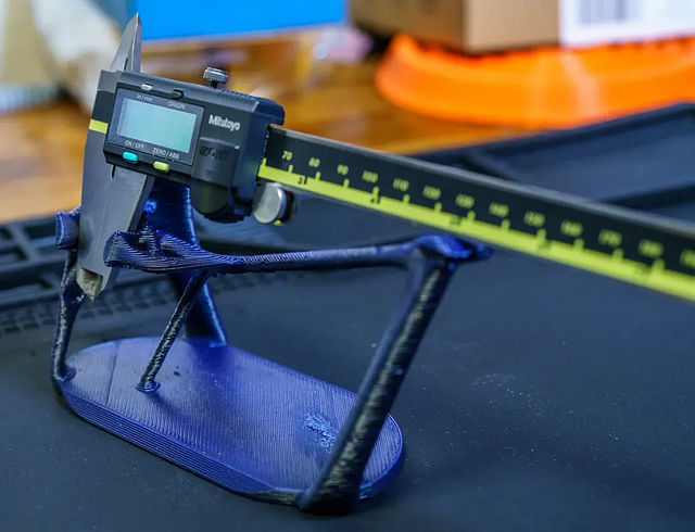
I've printed them from both resin and FDM, but I'm a bit partial to the resin ones thanks to the smooth surface finish.
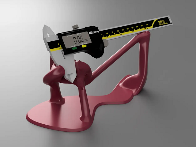
Thanks to “Gabriel Fraga” on GrabCAD for the great caliper model!
Description: A little combo of Generative Design and Kinematic Constraint (how many cool words can ya stuff into a simple stand!?) It holds calipers. I designed two variations, one for my 6” Mitutoyos and one for my 8” Mituoyos….yeah, I’m sorta partial on my caliper brand ¯\(ツ)/¯ But, I have also used them with a handful of different brands and sizes, with results ranging from “meh, it’s fine” to “seems the same as the designed”. In my experience, the biggest factor that pushes it to the former mainly just comes down to the jaw geometry.
The 6 inch stand (shown above) and the 8 inch stand (shown below) were designed with the same basic approach to the Generative Design constraints described below.
The Design
This isn’t intended to be a ‘how to’ for using the Fusion360 Generative Design extension (nor is it me endorsing that particular product. I have used it for a handful of projects, but I can’t say that I think it’s cost-effective for the vast majority of people currently.) Instead, I just wanted to give a quick description of my thought process in the design of this little desk accent.
The below sketch (believe it or not, the product of a full grown adult, and not a small child) is meant to show the approximate Center of Gravity (the darker, down arrow in the center), along with my planned locations for the support points.

From here, it’s time to jump into Fusion360 and create some bodies at these support points and apply Load Cases. The below image shows the bodies that I created in the 6 in model. The two partial cylinders on the left make tangential contact against the jaws. The hemisphere contacts the back plane of the calipers, on the ground metal surface. The L-shaped contact on the right primarily provides a vertical support on the slide, but it also may provide some lateral support also (more on this below.) These bodies will be my “Preserve Geometries”. These are going to end up being a part of the final component.
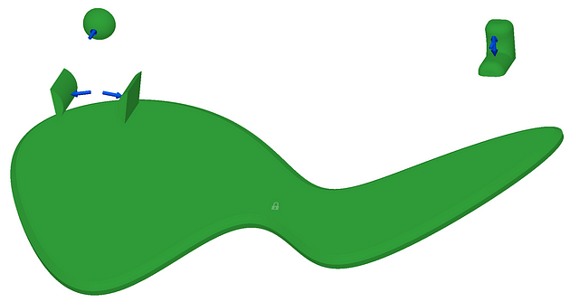
This constraint scheme ain’t exactly exact, but hear me out…it’s fine :). What I probably should have done would have been to add an additional contact like the hemisphere, but just moved down slightly. That would have constrained that degree of potential rotation, as well as the translation along the vector path normal to the plane through the cylindrical force vectors….too much? Especially without additional supporting imagery?…Well, my hunch is no one is going to read this, let alone care THAT much about this level of detail on kinematic constraint, so I’m just gonna call this part here…
If you want to learn more about the concept of Exact Constraint, this book is my favorite on the topic. You can also learn more by just searching around on exact constraint, or also, commonly “kinematic constraint” or “kinematic design”…stuff like that. It will also usually get a chapter or so in most texts on Precision Engineering.
Now on to another vital part of the setup for the GD inputs, and that’s the “Obstacle Geometries”. You can think of these as “keep out zones” for the solver.
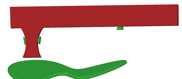
In the above you can see where I’ve added my ‘keep out’ zone for the calipers. I need to block out not only the space for the caliper in the final stand, but also any space that needs to be clear for getting them in and out of the stand, etc.
For this model, the Obstacles really are pretty straightforward. I essentially just added some margin around the calipers and then extended it out forward to ensure a clear path along that direction for inserting/removing the calipers from the stand.
Alright, we have our Preserve and Obstacle Geometries, and we have our Constraints and Loads applied. I can then run the simulation…it’s going to sit at “5%” for a shockingly long time…:)
And here are the results!
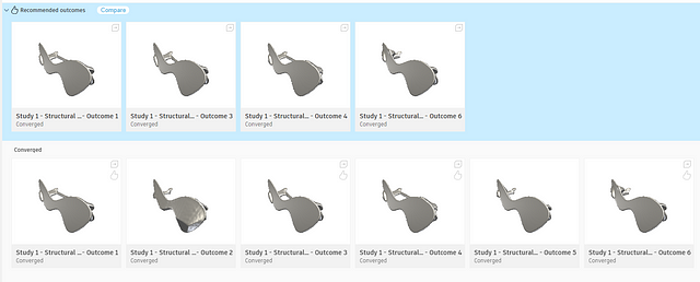
From here I just selected the outcome that I felt was most print-friendly and aesthetically pleasing, and that’s about that!
If you have any questions or comments, let me hear em! Thanks so much for checking it out! And if you’d like to see another of my generative design projects, you can take a look at my GD SD Card Tree.
Oh, and please note, I’m not saying this is THE way to design parts with Generative Design tools, this is just A way, and it’s a way that I enjoy :)
Desktop Caliper Stand
*PCBWay community is a sharing platform. We are not responsible for any design issues and parameter issues (board thickness, surface finish, etc.) you choose.
- Comments(0)
- Likes(0)
- 0 USER VOTES
- YOUR VOTE 0.00 0.00
- 1
- 2
- 3
- 4
- 5
- 6
- 7
- 8
- 9
- 10
- 1
- 2
- 3
- 4
- 5
- 6
- 7
- 8
- 9
- 10
- 1
- 2
- 3
- 4
- 5
- 6
- 7
- 8
- 9
- 10
- 1
- 2
- 3
- 4
- 5
- 6
- 7
- 8
- 9
- 10
 More by Bubs Builds
-
 3 channel valve assembly
Full build details available hereI had the Cam Retainer part printed from aluminum (and it came out ...
-
 Thermistor Driver Board
This board was made in support of the below video for getting temperature measurements using some be...
-
 8 channel valve assembly
Full build details available hereI had the Cam Retainer part printed from aluminum (and it came out ...
-
 6 channel valve assembly
Full build details available hereI had the Cam Retainer part printed from aluminum (and it came out ...
-
 High Flow Peristaltic Pump
Build BOMPrinted PartsI printed all of my parts in PETG, from a mixture of SUNLU and Polymaker fila...
-
 Displacement Sensor Flexure
As featured on Hackaday: https://hackaday.com/2024/05/18/flexures-keep-this-printed-displacement-sen...
-
 Folding Table Leg Hinge
A fellow Printables user recently asked me whether I thought any of my 2020 extrusion hinges would b...
-
 Flexure-based Fractal Vise Jaws
OverviewI, like pretty much every engineer I know, was absolutely enamored with the idea of fractal ...
-
 Bolt Sorting Sieve Shaker
Every project I work on that includes fasteners seems to end up accumulating a pile of unsorted, ran...
-
 Desktop Caliper Stand
A tidy way to keep your calipers handy. These stands were designed to hold 6 inch (150mm) or 8 inch ...
-
 Prusa Camera Mount
Original articleLike a lot of people, I love me a 3d printing time lapse. I've experimented with a f...
-
-
mammoth-3D SLM Voron Toolhead – Manual Drill & Tap Edition
207 0 0 -
-
AEL-2011 Power Supply Module
730 0 2 -
AEL-2011 50W Power Amplifier
607 0 2 -
-
-
Custom Mechanical Keyboard
812 0 0 -
Tester for Touch Screen Digitizer without using microcontroller
438 2 2 -
Audio reactive glow LED wristband/bracelet with NFC / RFID-Tags
391 0 1 -
-


