|
|
MINIWARE MHP30 Mini Hot Plate Preheater |
|
|
|
Soldering Iron Kit |
|
|
|
Soldering Iron Wire |
|
|
|
Tweezers for PCB |
|

|
arduino IDEArduino
|
ESP8266 ESP-12F DRV8848 Motor Driver Development Board
Line Following - Obstacle Avoiding - Drawing Robot
(ESP8266 Dual DC Motor Controller Board)
Hi everyone! In this project, I designed a board that includes the ESP8266 (ESP-12F) WiFi module, allowing you to control sensors such as HC-SR04 ultrasonic and infrared (IR), a servo and dual DC motors (DRV8848). To test the development board, we're going to build a small but fun 3D robot and control it, let's get started!
Supplies
- ESP-12F DRV8848 Driver Development Board
- HC-SR04 Ultrasonic Sensor
- Infrared (IR) Sensor
- Micro Servo Motor
- Dual Gear DC Motors (600RPM 6V)
- 3D Parts (SMARS Modular Robot)
- 11.1V 3S Lipo Battery
- Pliers
- Some Filament
- Two each with a bolt, nut and washer
- Water-Based Acrylic Paint for 3D Parts (Optional)
3D Parts of the Robot Chassis
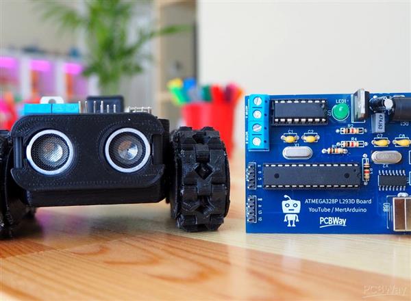
Followers will remember, I previously designed a board based on Atmega328 with L293D motor driver and used a 3D robot chassis. I will use the same chassis in this project, but the parts of the chassis are very deformed, so I used PCBWay's 3D printing service when ordering the printed circuit board.
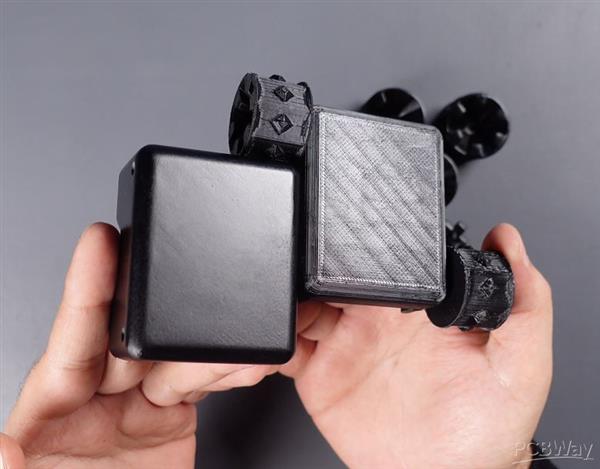
One of the best things about PCBWay is that it provides many services such as PCB, stencil, 3D and CNC that you need while doing a project. The new 3D parts were produced with SLA printing. A type of resin material is used thus providing dimensional accuracy, smooth surface and excellent detail. The previous 3D parts are FDM printing. PLA material is used for low-cost, non-functional prototyping. You can see the difference in quality between the parts when the models are compared.

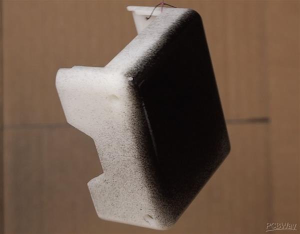
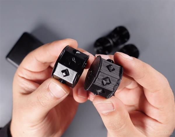
Before we move on to the printed circuit board, let's paint the 3D parts black with acrylic spray paint. Thus, there will be color harmony with other additional 3D parts of the robot. For this you will need a box and water-based acrylic paint. We place the 3D parts to be painted in the box and apply the spray paint as a thin layer on the part surfaces.
Printed Circuit Board - ESP-12F DRV8848 Driver Board

Until the 3D parts are dry, let's take a closer look at the printed circuit board. Printed circuit boards are preferred for long-term use, stable and more durable electronic circuit prototypes.
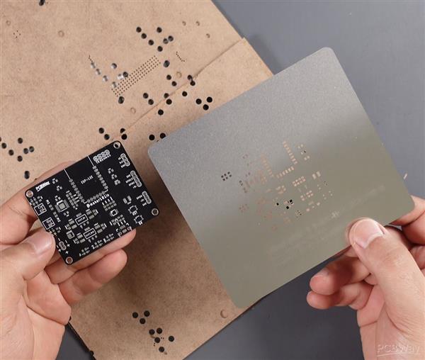
Some "surface mount device" components are preferred in this board, this affects the size and cost of the board design. For the assembly of SMD components, a stencil is generally preferred. Solder stencils help to accurately apply solder paste in position of components and the stencil is usually ordered with the printed circuit board.
The Process of Applying Solder Paste Using a Stencil
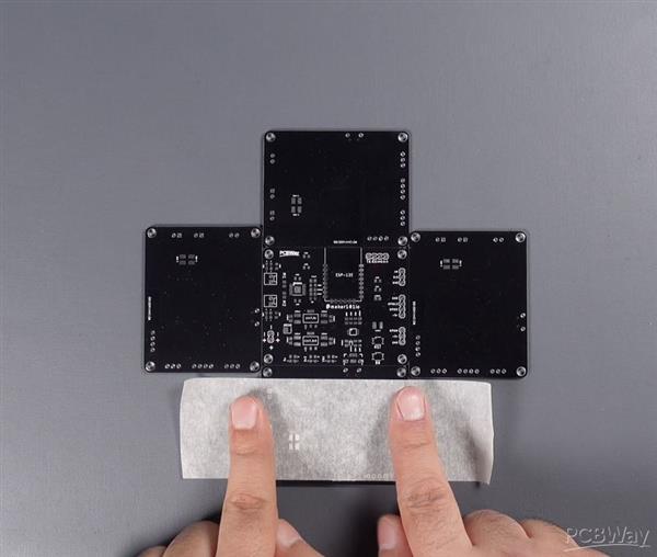

Solder stencils help to accurately apply solder paste in position of components. The process of applying solder paste using a stencil is simple, first fix the printed circuit board and place the stencil to match the board.
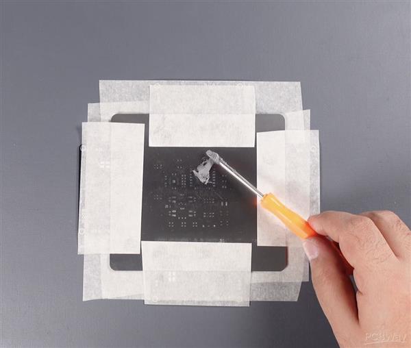
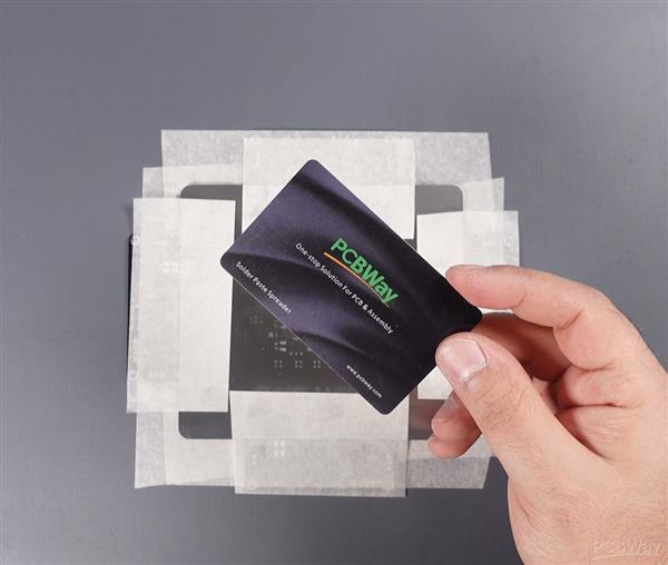
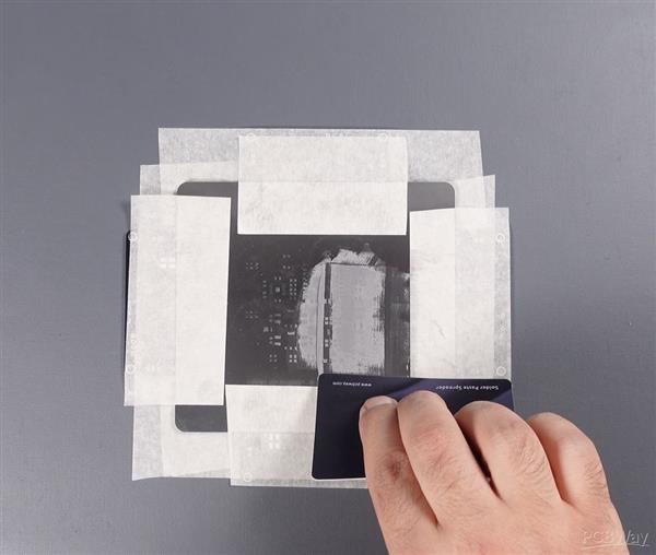
Then put some solder paste on the stencil with the help of a spoon and spread it with a spatula.
Here are some materials you need for this step:
- Solder Paste
- Masking Tape
- Solder Paste Spreader
Placement of Components on PCB and Soldering Process
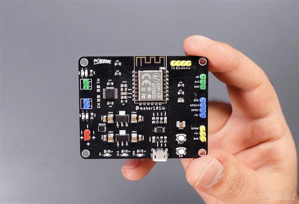
After applying the solder paste, it is necessary to place the required components on the board. Where to place these components is usually indicated by a designator or footprint reference. These references are used as part of the PCB design and ensure the correct placement of components. Designator shows what a component is and where it is located.
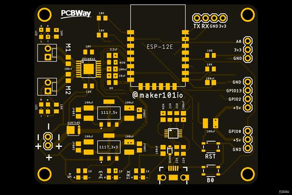
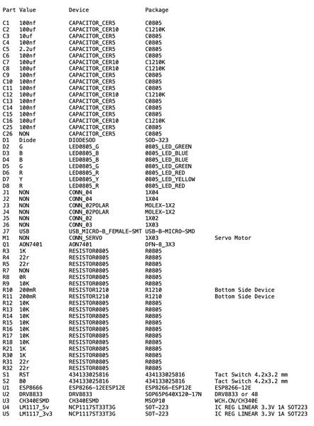
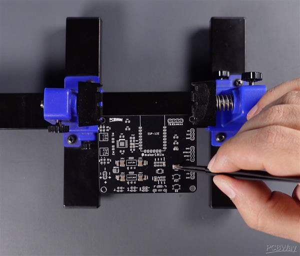
After the components are placed on the solder pads with the help of solder paste, the soldering process begins. Soldering is usually done with a hot plate machine or a hand soldering iron. The soldering machine heats and melts the solder paste and fixes the components in place. After the soldering is complete, the components are completely fixed in place when the solder paste has cooled.
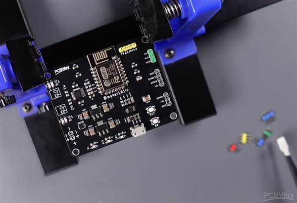
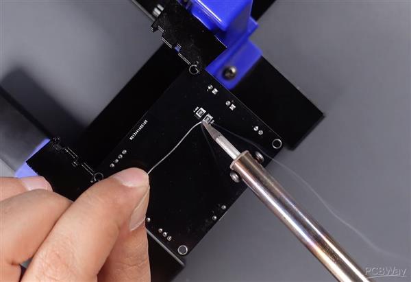
After soldering a few more components, the board will be complete. These components are a few headers and resistor. It can be easily soldered with a soldering iron.
Thanks for your interest, you can take a look at this project as an article on Instructables


ESP8266 ESP-12F DRV8848 Motor Driver Development Board
*PCBWay community is a sharing platform. We are not responsible for any design issues and parameter issues (board thickness, surface finish, etc.) you choose.
- Comments(1)
- Likes(7)
-
 Engineer
Sep 05,2024
-
 Engineer
Jul 22,2024
-
 Engineer
Mar 01,2024
-
 Engineer
Dec 19,2023
-
 Camilo Parra
Apr 12,2023
-
 MERT KILIC
Apr 12,2023
-
 Jason Bonitas
Apr 06,2023
- 2 USER VOTES
- YOUR VOTE 0.00 0.00
- 1
- 2
- 3
- 4
- 5
- 6
- 7
- 8
- 9
- 10
- 1
- 2
- 3
- 4
- 5
- 6
- 7
- 8
- 9
- 10
- 1
- 2
- 3
- 4
- 5
- 6
- 7
- 8
- 9
- 10
- 1
- 2
- 3
- 4
- 5
- 6
- 7
- 8
- 9
- 10

-
10design
-
10usability
-
10creativity
-
10content
-
10design
-
10usability
-
10creativity
-
10content
 More by MERT KILIC
-
 3D Printed Theo Jansen Style Octopod Robot (Arduino Based)
Hi everyone! In this project, I will show you an amazing eight-legged robot in the Octopod style! It...
-
 Creative Modular LED Lighting with Magnetic Pogo Pins & Wi-Fi Control
Hi everyone! Welcome to my latest project: a modular, plug-in LED lighting system that is as fun as ...
-
 Build a simple 3D printed CNC plotter machine
Hi friends, do you remember this Mini CNC Plotter machine that uses hobby stepper motors and a few 3...
-
 Circuit Activity Board - Educational Electronics
Circuit Activity Board – A Hands-On Project to Learn Basic ElectronicsIn this project, we're going t...
-
 Build a Simple 3D Wall Lighting
Hi friends, this project shows how to make and control 3D hexagonal LED lighting panels. The project...
-
 Robot Sumo Board
Robot-sumo, or pepe-sumo, is a sport in which two robots attempt to push each other out of a circle ...
-
 ESP32 Mecanum Wheels Robot and Bluetooth Gamepad Controller
In this project we will see how to make an ESP32 Mecanum Wheels Robot which is capable of moving in ...
-
 DIY Motorized WiFi Roller Blind - ESP8266 & Blynk
In this project we will see how to control a roller blind via a smartphone application. The reason w...
-
 Pet Feeder Controlled Via WiFi - ESP8266
How It Works?As you can see, a 3D design was used for the pet feeder. ESP8266-based Wemos D1 Mini bo...
-
 ESP8266 Two Wheel Robot (NodeMCU and Stepper Motor)
Generally, robot cars are built on a chassis with 2 DC motor wheels and a bovine wheel. While surfin...
-
 3D Printed Rotating Table Board with Arduino Nano and 28BYJ-48 Stepper Motor
This project shows how to make a 3D printed Rotating Table using Arduino and a hobby stepper motor. ...
-
 Hand Gesture Controller for Robotic
The hand gesture controller makes it possible to control applicat...
Hand Gesture Controller for Robotic
Hand Gesture Controller for RoboticThe hand gesture controller makes it possible to control applicat...
-
 How To Make DIY Remote Control Hoverboat at Home
In this video, I showed you how to make your own hoverboat from materials available at home and chea...
-
 How to Make DIY Arduino Gesture Control Robot at Home
Parts Required for Receiver (Tank):1) Robot Tank Chassis - https://bit.ly/3j8y2Q52) Arduino Nano V3 ...
-
 DIY Circuit Activty Board with Paperclips | MAKER | STEM
You can be creative and design your own circuit and add different sensors (other LEDs...). The idea ...
-
 ATtiny85 Wearable Activity Tracking Watch
How to make the wearable activity tracking watch? This is a wearable gadget designed to vibrate when...
-
 How to Build a Motorized 3D Scanning Turntable for Your Phone
In this project, I’ll show you how to make a simple motorized turntable for 3D scanning. It has thre...
-
 DIY Motorized 3D Scanning Turntable
In this project, I’ll show you how to make a simple motorized turntable for 3D scanning. It has thre...
-
-
mammoth-3D SLM Voron Toolhead – Manual Drill & Tap Edition
140 0 0 -
-
AEL-2011 Power Supply Module
653 0 2 -
AEL-2011 50W Power Amplifier
567 0 2 -
-
-
Custom Mechanical Keyboard
769 0 0 -
Tester for Touch Screen Digitizer without using microcontroller
395 2 2 -
Audio reactive glow LED wristband/bracelet with NFC / RFID-Tags
363 0 1 -
-


