


GPS UTC clock
I wanted a UTC time clock when logging contacts with my amateur radios and the option to set my PC clock..
Sept 2022 New board now designed and made will share once I have tested the board.
This PCB board was designed to interface a NEO-7M GPS and Arduino Nano to a 1602 LCD Display in a compact form that will fit inside a Transparent Acrylic LCD Shell for 1602 LCD display.
The time and date are set by a GPS and display the UTC time on a 1602 display, can also be programed to send data via USB.
Code for the Arduino Nano can easily be changed to display local time and other data available from the GPS, like the location or grid square, a quick search on the internet will find lots of programing options and suitable code, just change the LCD and GPS pins in the code to suit the board.
The 1602 display is connected to the Arduino Nano using pins RS-D8, E-D9, D4-D10, D5-D11, D6-D12, D7-D13 and the GPS is connected using RX to D3 and TX to D4, The LCD 16 pin header socket, is fitted to the bottom of the board
I have added the option of a pin (J3) for the PPS out from the GPS, a pin is not required unless using the PPS output from the GPS.
It should be possible to interface other GPS modules to this board but the interface pins and module size would have to match or be connected via wires and the GPS mounted somewhere else.
This project can be powered by a USB cable connection to the Arduino Nano or via an optional 7 to 20VDC external supply (I Had 6.5 to 12VDC marked on the board but the LM7805 can go up to 25VDC, Have changed in ver 1.1) if using a USB cable then J2 has the middle and internal pin (opposite end to J1) shorted with a jumper or header pin jumper. The following components are only needed if an external DC power supply is used, C1-2, U1, J1,
It would also be possible to use a 5V external supply and bypass the regulator circuit, just a few jumpers in the right place.
RV1 is used to change the contrast on the LCD.
RV2 is used to change the brightness of the display and can be less that 10kΩ, was convenient to use 2 the same, a fixed resistor about 220Ω can be used instead but it’s nice to be able to adjust the brightness of the backlight LED.
If using a Transparent Acrylic LCD Shell for 1602 LCD display then a hole will be needed in the side of the case for the GPS antenna if fitted to GPS module, also check the position of J2, it just touches the back section of the case, might be worth putting a small notch in the Perspex to allow some clearance, will then be easier to move the jumper. ver 1.1 Have moved J2 slightly and added the option to add extra headers for the spare Arduino Nano pins
A 2004 LCD display could be used or/and a different enclosure.
Remember the board was designed for the LCD 1602 header to be put on the back of the board. The LCD and board can be supported with a suitable spacers and bolts, recommended at least 2 opposite the headers if moving around for field use to reduce damage to the connecting headers.
Note: The mounting holes on ver 1 are just a bit small for 3mm bolts The holes are 2.7mm. (Changed in ver 1.1)
It is possible to use this board for other projects, I will be using this board for a Morse code oscillator and decoder by using the GPS socket to connect a key and amplifier board to a speaker, will look at the option of adding a few extra connections from the Arduino Nano for future projects, (done ver 1.1) may design a new board for the 2004 LCD which will allow more room for extra pins.
Version 1
Ver 1.1 files added 20 June 2020
Thanks for looking
Michael
VK6TU
GPS UTC clock
*PCBWay community is a sharing platform. We are not responsible for any design issues and parameter issues (board thickness, surface finish, etc.) you choose.


- Comments(5)
- Likes(7)
More by Michael vk6tu
-
 GPS UTC clock
I wanted a UTC time clock when logging contacts with my amateur radios and the option to set my PC c...
GPS UTC clock
I wanted a UTC time clock when logging contacts with my amateur radios and the option to set my PC c...
-
 Morse Code Display I2C LCD ver2-3
20 x 04 LCD Display that allows CW keyed with a Morse Code Key to be displayed as text.Using a Ardui...
Morse Code Display I2C LCD ver2-3
20 x 04 LCD Display that allows CW keyed with a Morse Code Key to be displayed as text.Using a Ardui...
-
 CW sounder kit 2.kicad_pcb
CW sounder solder project.CW sounder soldering project, simple design using a 555 timer IC to make a...
CW sounder kit 2.kicad_pcb
CW sounder solder project.CW sounder soldering project, simple design using a 555 timer IC to make a...
-
 Morse Code Station pcb
Board designed based on this page. https://hackaday.io/project/175129-arduino-morse-code-stationI us...
Morse Code Station pcb
Board designed based on this page. https://hackaday.io/project/175129-arduino-morse-code-stationI us...
-
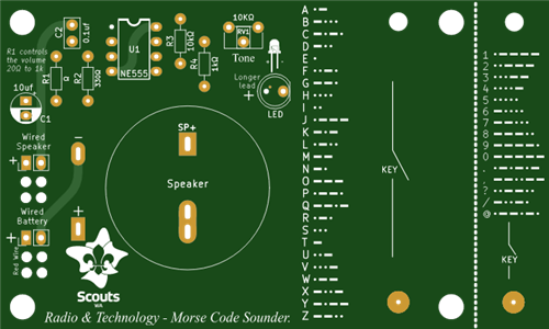
 CW sounder solder project
CW sounder soldering project, simple design using a 555 timer IC to make a CW sounder for scouts to ...
CW sounder solder project
CW sounder soldering project, simple design using a 555 timer IC to make a CW sounder for scouts to ...
-
 Control cable lightening protection
Protection circuit using a GDT, Varister, Zener and capacitor, all optional but each device adds mor...
Control cable lightening protection
Protection circuit using a GDT, Varister, Zener and capacitor, all optional but each device adds mor...
-
 GPS UTC clock ver 2.1
New board designed based on my original GPS UTC clockhttps://www.pcbway.com/project/shareproject/GPS...
GPS UTC clock ver 2.1
New board designed based on my original GPS UTC clockhttps://www.pcbway.com/project/shareproject/GPS...
-
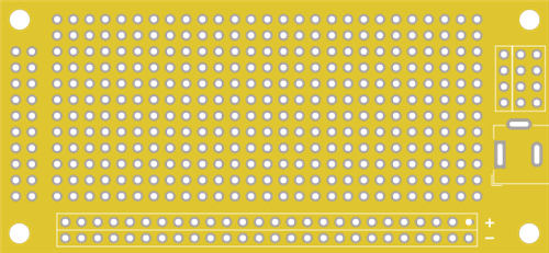 Strip board with power connection
Basic strip board for making simple projects 18 rows split in the middle for IC or similar mounting...
Strip board with power connection
Basic strip board for making simple projects 18 rows split in the middle for IC or similar mounting...
-
 TLL to RS232 DB9 board
This simple board was designed to allow the connection of older equipment that uses a DB9 serial por...
TLL to RS232 DB9 board
This simple board was designed to allow the connection of older equipment that uses a DB9 serial por...
-
-
-
-
Tester for Touch Screen Digitizer without using microcontroller
329 2 2 -
Audio reactive glow LED wristband/bracelet with NFC / RFID-Tags
310 0 1 -
-
-


