


Home Automation Board with NODEMCU Six Outputs
Hello and welcome back!
This is a Home Automation Board that is based around the NODEMCU ESP8266 Board and Six Relays neatly packed in a nice form factor.
We can attach AC or even DC loads with this setup as each relay's NO and NC ports are connected to a screw terminal, which we can connect loads in series with. This DIY home automation system uses an ESP8266 to operate six separate relays to switch six outputs or loads.
Every relay is controlled via a web application that may be accessed through any local network browser.
This device is version 2 of my earlier home automation board, which featured an esp07S module and only had two outputs. Version 2's use of nodemcu makes it simpler for the user to reprogram the board.
https://www.hackster.io/Arnov_Sharma_makes/home-automation-board-with-esp8266-dual-output-75f5b3
The goal of this project is to make an easy and simple Home Automation System that anyone can make and learn by following a few simple steps.
let's get started.
Material Required
Following were the components used in this built-
- Custom PCB
- Relays
- Nodemcu
- AO3400 Mosfets
- M7 Diodes
- 10K resistors
- SMD LEDs
- AC to DC Isolated SMPS
- Screw Terminal connectors
PCB Design
_SUTg2qXx5U.jpg?auto=compress%2Cformat&w=740&h=555&fit=max)

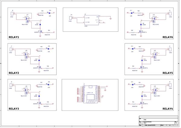
PCB The design of this board consists of eight parts, six of which have a relay connected to an N-channel mosfet, whose gate is coupled to the NODEMCU of another section.
A LED is also attached to the relay along with the Mosfet; this LED serves as an indicator and will turn on when the relay is switched.
NODEMCU is located in one portion, and it is connected to six Mosfets and six LED pins.
Then, an isolated 240V AC to 5V DC SMPS is also attached to the board and connected with a screw terminal connector in order to power the entire arrangement with 240V AC. We will connect an AC cord to the SMPS's screw terminal in order to do this.
We prepare the board design and neatly organize all the components in a 120mm x 70mm form factor after the schematic is complete.
For isolation purposes, slots were inserted between the AC pins and the DC components.
A relay with a mosfet as a switch configuration and leds are located on the bottom half of the PCB, which also houses the SMPS on the right side.
PCBWAY Service


After the PCB Design was completed, Gerber data was generated and then sent to PCBWAY for samples.
An order was placed for the PCBs with white soldermask and black silkscreen, as it looks pretty cool in general.
In terms of overall quality, it was outstanding. Each of the 10 boards I bought was flawless.
Really love the quality of PCBs made by PCBWAY. There are other manufacturers available, but their service is always on another level.
check out PCBWay service for getting great PCB service at less cost.
Solderpaste and PNP Process


Board Assembly Process begins by first adding solder paste to each component pad one by one.
Next, using a tweezer, we pick and position each SMD component in its designated location.
Hotplate Reflow


Following that, we carefully lifted the entire circuit board and set it down on the SMT Hotplate, which heats the PCB from below up to the solder paste melting temperature. As soon as the PCB reaches that temperature, the solder paste melts, and all the components are connected to their pads.
THT Components


Next, we add THT components in their location and solder the pads by using a soldering iron.
Board assembly is now completed.
Result so far

Here is the final result of the board assembly process: a rectangular, soldered Home Automation board with six relays and an SMPS power supply that can be connected to any setup (AC or DC) to make it into a smart controllable load.
Adding Nodemcu to the Home AUT Board


The board is complete but is missing one of its most crucial components, which is the NOCEMCU board.
We add NODEMCU in its place through female header pins soldered onboard.
Test Sketch

The test sketch, which is actually a chaser sketch, is uploaded to the ESP Board. Its main function is to sequentially toggle each output pin to show how the board functions.
Relays are connected with D0 to D5 and LED are connected with D6, D7, D8, TX, RX and GPIO8 of the Nodemcu.
The chaser sketch makes sure that each output is operational, allowing us to move on to the next step, which is attaching an AC cord to this arrangement and running the main code into it.
Adding AC Cord

We connect the live and neutral ends of an AC cord to the screw terminals on the SMPS supply in order to power the board using an AC source.
Main Sketch

Check out the main sketch, which is attached in the code section.
- We first edit the SSID and PASSWORD in the sketch
- next we upload the code into the NODEMCU and open the serial monitor.
- We then copy the IP Address shown when the ESP gets connected to WiFi and paste the IP Address into any browser.
- WEB APP will open up which can be used to toggle six outputs.
The web app is completely customized and is made completely from a single sketch without using any third-party tools.
This sketch is a fusion of classic embedded C language and HTML with a little bit of CSS.
We set up the HTML page in this sketch by the below lines.
// Display the HTML web page client.println("<!DOCTYPE html><html>"); client.println("<head><meta name=\"viewport\" content=\"width=device-width, initial-scale=1\">"); client.println("<link rel=\"icon\" href=\"data:,\">"); // CSS to style the on/off buttons // Feel free to change the background-color and font-size attributes to fit your preferences client.println("<style>html { font-family: Helvetica; display: inline-block; margin: 0px auto; text-align: center;}"); client.println(".button { background-color: #5B196A; border: none; color: white; padding: 16px 40px;"); client.println("text-decoration: none; font-size: 30px; margin: 2px; cursor: pointer;}"); client.println(".button2 {background-color: #5B196A;}</style></head>"); // Web Page Heading client.println("<body><h1>HOME AUTOMATION DUAL OUTPUT</h1>"); // Display current state, and ON/OFF buttons for OUTPUT1 client.println("<p>LOAD1 - State " + output1State + "</p>");
Please note that this setup will only work if the ESP8266 and the device that you're browsing the APP on the same network.(LOCAL NETWORK OPERATION)
Conclusion
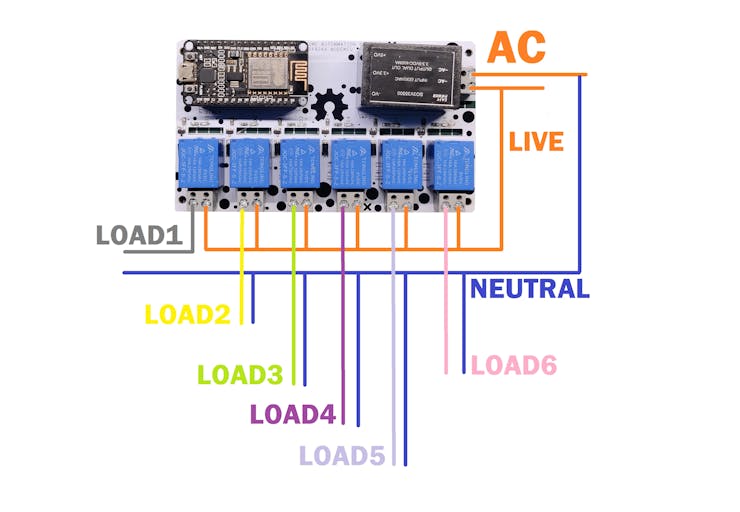
This device can be connected to the MCB Box in our home to regulate a particular region or close to any lighting switch that controls at least six light outputs by using the wiring diagram that is included.
The way it works is also simple, relays are like physical switches, and we can add them in series with any light source or output. By changing the state of RELAY to HIGH or LOW, it can break or connect the circuit and control the load connected to it.
This is it for today, folks, Do leave a comment if you have any trouble setting up this project.
Check out my previous home automation projects if you're interested in this topic.
https://www.hackster.io/Arnov_Sharma_makes/home-automation-getting-started-guide-7a8185#toc-conclusion-and-improvement-13
https://www.hackster.io/Arnov_Sharma_makes/home-automation-board-with-esp8266-dual-output-75f5b3
Special thanks to PCBWAY for providing components that I've used in this project, check them out for getting all sorts of PCB or PCBA-related services for less cost.
Thanks and I will be back with a new project soon.
int pinsCount=13;                        // declaring the integer variable pinsCount
int pins[] = {16,5,4,0,2,14,12,13,15,3,1};          // declaring the array pins[]


void setup() {
  pinMode(16, OUTPUT);
  pinMode(5, OUTPUT);
  pinMode(4, OUTPUT);
  pinMode(0, OUTPUT);
  pinMode(2, OUTPUT);
  pinMode(14, OUTPUT);
  pinMode(12, OUTPUT);
  pinMode(13, OUTPUT);
  pinMode(15, OUTPUT);
  pinMode(3, OUTPUT);
  pinMode(1, OUTPUT);
//  pinMode(8, OUTPUT);

}


void loop() {
  for (int i=0; i<pinsCount; i=i+1){    // chasing right
    digitalWrite(pins[i], HIGH);         // switching the LED at index i on
    delay(500);                          // stopping the program for 100 milliseconds
    digitalWrite(pins[i], LOW);          // switching the LED at index i off
  }
  for (int i=pinsCount-1; i>0; i=i-1){   // chasing left (except the outer leds)
    digitalWrite(pins[i], HIGH);         // switching the LED at index i on
    delay(500);                          // stopping the program for 100 milliseconds
    digitalWrite(pins[i], LOW);          // switching the LED at index i off
  }

}
#include <ESP8266WiFi.h>

// Webserver Config
const char *ssid = "YOUR SSID";
const char *password = "YOUR PASS";

// Set web server port number to 80
WiFiServer server(80);

// Variable to store the HTTP request
String header;

// Auxiliar variables to store the current output state
String output1State = "off";
String output2State = "off";
String output3State = "off";
String output4State = "off";
String output5State = "off";
String output6State = "off";


// Assign output variables to GPIO pins
const int output1 = 16; //D0
const int output2 = 5;  //D1
const int output3 = 4;  //D2
const int output4 = 0;  //D3
const int output5 = 2;  //D4
const int output6 = 14;  //D5

void setup() {
  Serial.begin(115200);
  // Initialize the output variables as outputs
  pinMode(output1, OUTPUT);
  pinMode(output2, OUTPUT);
  pinMode(output3, OUTPUT);
  pinMode(output4, OUTPUT);
  pinMode(output5, OUTPUT);
  pinMode(output6, OUTPUT);

  // Set outputs to HIGH
  digitalWrite(output1, HIGH);
  digitalWrite(output2, HIGH);
  digitalWrite(output3, HIGH);
  digitalWrite(output4, HIGH);
  digitalWrite(output5, HIGH);
  digitalWrite(output6, HIGH);

  // Connect to Wi-Fi network with SSID and password
  Serial.print("Connecting to ");
  Serial.println(ssid);
  WiFi.begin(ssid, password);
  while (WiFi.status() != WL_CONNECTED) {
    delay(500);
    Serial.print(".");
  }
  // Print local IP address and start web server
  Serial.println("");
  Serial.println("WiFi connected.");
  Serial.println("IP address: ");
  Serial.println(WiFi.localIP());
  server.begin();
}

void loop(){
  WiFiClient client = server.available();   // Listen for incoming clients

  if (client) {                             // If a new client connects,
    Serial.println("New Client.");          // print a message out in the serial port
    String currentLine = "";                // make a String to hold incoming data from the client
    while (client.connected()) {            // loop while the client's connected
      if (client.available()) {             // if there's bytes to read from the client,
        char c = client.read();             // read a byte, then
        Serial.write(c);                    // print it out the serial monitor
        header += c;
        if (c == '\n') {                    // if the byte is a newline character
          // if the current line is blank, you got two newline characters in a row.
          // that's the end of the client HTTP request, so send a response:
          if (currentLine.length() == 0) {
            // HTTP headers always start with a response code (e.g. HTTP/1.1 200 OK)
            // and a content-type so the client knows what's coming, then a blank line:
            client.println("HTTP/1.1 200 OK");
            client.println("Content-type:text/html");
            client.println("Connection: close");
            client.println();

            // turns the GPIOs on and off
            if (header.indexOf("GET /1/on") >= 0) {         //LOAD1
              Serial.println("LOAD1 on");
              output1State = "on";
              digitalWrite(output1, LOW);
            } else if (header.indexOf("GET /1/off") >= 0) {
              Serial.println("LOAD1 off");
              output1State = "off";
              digitalWrite(output1, HIGH);
            } else if (header.indexOf("GET /2/on") >= 0) {  //LOAD2
              Serial.println("LOAD2 on");
              output2State = "on";
              digitalWrite(output2, LOW);
            } else if (header.indexOf("GET /2/off") >= 0) {
              Serial.println("LOAD2 off");
              output2State = "off";
              digitalWrite(output2, HIGH);
            } else if (header.indexOf("GET /3/on") >= 0) {  //LOAD3
              Serial.println("LOAD3 on");
              output3State = "on";
              digitalWrite(output3, LOW);
            } else if (header.indexOf("GET /3/off") >= 0) {
              Serial.println("LOAD3 off");
              output3State = "off";
              digitalWrite(output3, HIGH);
            } else if (header.indexOf("GET /4/on") >= 0) {   //LOAD4
              Serial.println("LOAD4 on");
              output4State = "on";
              digitalWrite(output4, LOW);
            } else if (header.indexOf("GET /4/off") >= 0) {
              Serial.println("LOAD4 off");
              output4State = "off";
              digitalWrite(output4, HIGH);
            } else if (header.indexOf("GET /5/on") >= 0) {   //LOAD5
              Serial.println("LOAD5 on");
              output5State = "on";
              digitalWrite(output5, LOW);
            } else if (header.indexOf("GET /5/off") >= 0) {
              Serial.println("LOAD5 off");
              output5State = "off";
              digitalWrite(output5, HIGH);
            } else if (header.indexOf("GET /6/on") >= 0) {   //LOAD6
              Serial.println("LOAD6 on");
              output6State = "on";
              digitalWrite(output6, LOW);
            } else if (header.indexOf("GET /6/off") >= 0) {
              Serial.println("LOAD6 off");
              output6State = "off";
              digitalWrite(output6, HIGH);
            }


            // Display the HTML web page
            client.println("<!DOCTYPE html><html>");
            client.println("<head><meta name=\"viewport\" content=\"width=device-width, initial-scale=1\">");
            client.println("<link rel=\"icon\" href=\"data:,\">");
            client.println("<style>html { font-family: Helvetica; display: inline-block; margin: 0px auto; text-align: center;}");
            client.println(".button { background-color: #6a195b; border: none; color: white; padding: 16px 40px;");
            client.println("text-decoration: none; font-size: 30px; margin: 2px; cursor: pointer;}");
            client.println(".button2 {background-color: #a82890;}</style></head>");

            // Web Page Heading
            client.println("<body><h1>HOME AUTOMATION BASIC</h1>");

            // Display current state, and ON/OFF buttons for OUTPUT1
            client.println("<p>LOAD1 - State " + output1State + "</p>");

            // If the output1State is off, it displays the ON button
            if (output1State=="off") {
              client.println("<p><a href=\"/1/on\"><button class=\"button\">ON</button></a></p>");
            } else {
              client.println("<p><a href=\"/1/off\"><button class=\"button button2\">OFF</button></a></p>");
            }

            // Display current state, and ON/OFF buttons for OUTPUT2
            client.println("<p>LOAD2 - State " + output2State + "</p>");

            // If the output2State is off, it displays the ON button
            if (output2State=="off") {
              client.println("<p><a href=\"/2/on\"><button class=\"button\">ON</button></a></p>");
            } else {
              client.println("<p><a href=\"/2/off\"><button class=\"button button2\">OFF</button></a></p>");
            }


           // Display current state, and ON/OFF buttons for OUTPUT3
            client.println("<p>LOAD3 - State " + output3State + "</p>");


           // If the output3State is off, it displays the ON button
            if (output3State=="off") {
              client.println("<p><a href=\"/3/on\"><button class=\"button\">ON</button></a></p>");
            } else {
              client.println("<p><a href=\"/3/off\"><button class=\"button button2\">OFF</button></a></p>");
            }

           // Display current state, and ON/OFF buttons for OUTPUT4
            client.println("<p>LOAD4 - State " + output4State + "</p>");


           // If the output4State is off, it displays the ON button
            if (output4State=="off") {
              client.println("<p><a href=\"/4/on\"><button class=\"button\">ON</button></a></p>");
            } else {
              client.println("<p><a href=\"/4/off\"><button class=\"button button2\">OFF</button></a></p>");
            }

            // Display current state, and ON/OFF buttons for OUTPUT5
            client.println("<p>LOAD5 - State " + output5State + "</p>");


           // If the output5State is off, it displays the ON button
            if (output5State=="off") {
              client.println("<p><a href=\"/5/on\"><button class=\"button\">ON</button></a></p>");
            } else {
              client.println("<p><a href=\"/5/off\"><button class=\"button button2\">OFF</button></a></p>");
            }

            // Display current state, and ON/OFF buttons for OUTPUT6
            client.println("<p>LOAD6 - State " + output6State + "</p>");


           // If the output6State is off, it displays the ON button
            if (output6State=="off") {
              client.println("<p><a href=\"/6/on\"><button class=\"button\">ON</button></a></p>");
            } else {
              client.println("<p><a href=\"/6/off\"><button class=\"button button2\">OFF</button></a></p>");
            }


            client.println("</body></html>");

            // The HTTP response ends with another blank line
            client.println();
            // Break out of the while loop
            break;
          } else { // if you got a newline, then clear currentLine
            currentLine = "";
          }
        } else if (c != '\r') {  // if you got anything else but a carriage return character,
          currentLine += c;      // add it to the end of the currentLine
        }
      }
    }
    // Clear the header variable
    header = "";
    // Close the connection
    client.stop();
    Serial.println("Client disconnected.");
    Serial.println("");
  }
}
Home Automation Board with NODEMCU Six Outputs
*PCBWay community is a sharing platform. We are not responsible for any design issues and parameter issues (board thickness, surface finish, etc.) you choose.


- Comments(0)
- Likes(7)
 More by Arnov Arnov sharma
-
 Pocket SNES
Greetings everyone, and welcome back! Today, I’ve got something fun and tiny to share—the Pocket SNE...
Pocket SNES
Greetings everyone, and welcome back! Today, I’ve got something fun and tiny to share—the Pocket SNE...
-
 Batocera Arcade Box
Greetings everyone and welcome back, Here's something. Fun and nostalgic. Right now, we are using ou...
Batocera Arcade Box
Greetings everyone and welcome back, Here's something. Fun and nostalgic. Right now, we are using ou...
-
 64x32 Matrix Panel Setup with PICO 2
Greetings everyone and welcome back.So here's something fun and useful: a Raspberry Pi Pico 2-powere...
64x32 Matrix Panel Setup with PICO 2
Greetings everyone and welcome back.So here's something fun and useful: a Raspberry Pi Pico 2-powere...
-
 Portable Air Quality Meter
Hello everyone, and welcome back! Today, I have something incredibly useful for you—a Portable Air Q...
Portable Air Quality Meter
Hello everyone, and welcome back! Today, I have something incredibly useful for you—a Portable Air Q...
-
 WALKPi PCB Version
Greetings everyone and welcome back, This is the WalkPi, a homebrew audio player that plays music fr...
WALKPi PCB Version
Greetings everyone and welcome back, This is the WalkPi, a homebrew audio player that plays music fr...
-
 Delete Button XL
Greetings everyone and welcome back, and here's something fun and useful.In essence, the Delete Butt...
Delete Button XL
Greetings everyone and welcome back, and here's something fun and useful.In essence, the Delete Butt...
-
 Arduino Retro Game Controller
Greetings everyone and welcome back. Here's something fun.The Arduino Retro Game Controller was buil...
Arduino Retro Game Controller
Greetings everyone and welcome back. Here's something fun.The Arduino Retro Game Controller was buil...
-
 Super Power Buck Converter
Greetings everyone and welcome back!Here's something powerful, The SUPER POWER BUCK CONVERTER BOARD ...
Super Power Buck Converter
Greetings everyone and welcome back!Here's something powerful, The SUPER POWER BUCK CONVERTER BOARD ...
-
 Pocket Temp Meter
Greetings and welcome back.So here's something portable and useful: the Pocket TEMP Meter project.As...
Pocket Temp Meter
Greetings and welcome back.So here's something portable and useful: the Pocket TEMP Meter project.As...
-
 Pico Powered DC Fan Driver
Hello everyone and welcome back.So here's something cool: a 5V to 12V DC motor driver based around a...
Pico Powered DC Fan Driver
Hello everyone and welcome back.So here's something cool: a 5V to 12V DC motor driver based around a...
-
 Mini Solar Light Project with a Twist
Greetings.This is the Cube Light, a Small and compact cube-shaped emergency solar light that boasts ...
Mini Solar Light Project with a Twist
Greetings.This is the Cube Light, a Small and compact cube-shaped emergency solar light that boasts ...
-
 PALPi V5 Handheld Retro Game Console
Hey, Guys what's up?So this is PALPi which is a Raspberry Pi Zero W Based Handheld Retro Game Consol...
PALPi V5 Handheld Retro Game Console
Hey, Guys what's up?So this is PALPi which is a Raspberry Pi Zero W Based Handheld Retro Game Consol...
-
 DIY Thermometer with TTGO T Display and DS18B20
Greetings.So this is the DIY Thermometer made entirely from scratch using a TTGO T display board and...
DIY Thermometer with TTGO T Display and DS18B20
Greetings.So this is the DIY Thermometer made entirely from scratch using a TTGO T display board and...
-
 Motion Trigger Circuit with and without Microcontroller
GreetingsHere's a tutorial on how to use an HC-SR505 PIR Module with and without a microcontroller t...
Motion Trigger Circuit with and without Microcontroller
GreetingsHere's a tutorial on how to use an HC-SR505 PIR Module with and without a microcontroller t...
-
 Motor Driver Board Atmega328PU and HC01
Hey, what's up folks here's something super cool and useful if you're making a basic Robot Setup, A ...
Motor Driver Board Atmega328PU and HC01
Hey, what's up folks here's something super cool and useful if you're making a basic Robot Setup, A ...
-
 Power Block
Hey Everyone what's up!So this is Power block, a DIY UPS that can be used to power a bunch of 5V Ope...
Power Block
Hey Everyone what's up!So this is Power block, a DIY UPS that can be used to power a bunch of 5V Ope...
-
 Goku PCB Badge V2
Hey everyone what's up!So here's something SUPER cool, A PCB Board themed after Goku from Dragon Bal...
Goku PCB Badge V2
Hey everyone what's up!So here's something SUPER cool, A PCB Board themed after Goku from Dragon Bal...
-
 RGB Mixinator V2
Hey Everyone how you doin!So here's a fun little project that utilizes an Arduino Nano, THE MIXINATO...
RGB Mixinator V2
Hey Everyone how you doin!So here's a fun little project that utilizes an Arduino Nano, THE MIXINATO...
-
-
-
-
Tester for Touch Screen Digitizer without using microcontroller
341 2 2 -
Audio reactive glow LED wristband/bracelet with NFC / RFID-Tags
323 0 1 -
-
-


