|
fritzing |
|

|
Inkscape |
|

|
Soldering iron |
|

|
NI MultisimNI
|
ISLA Autonomous Robot
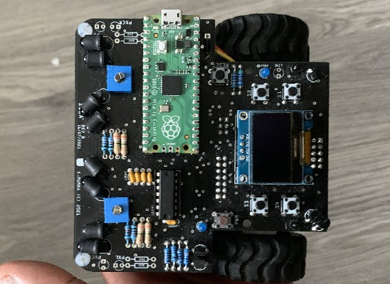
The ISLA Project is a DIY friendly autonomous robot using only mostly through hole components making this design very easy to implement for anyone with some money, a Raspberry Pi Pico and a soldering iron. I decided to make this because I wanted to create something that would be easy to make even for people who do not have access to specific equipment such as a reflow oven, a scope, or a 3D printer. The Design is powered by 4 AAA batteries, which are used to power the various sensors and the microcontroller. The microcontroller control the battery sensor, motors, proximity sensor and line sensor on the device. This is a brief description of the device, I will provide In detail technical documentation of the device in 2022. It is highly recommended to view the schematics before downloading the gerber file.
Microcontroller
This device is built around the Raspberry Pi Foundation's Arm Processor RP2040 microcontroller. The Raspberry Pi Pico is a very fast and efficient MCU, this application barely scratches the surface of its capabilities.
Indicators
- Power LED
- Sensor LED
- Buzzer
- OLED Display
Sensors
- 4x Infrared Proximity sensors
- 4x Infrared Line Sensors
- Battery Sensor
- 2x Motor Encoders
Power Management
The device uses a 5V buck-boost module to regulate its operating voltage, it requires a minimum input voltage of 4V to operate optimally. The output voltage of the buck boost is then used to power motors and 3.3V LDO.
The 3.3V LDO is required since the Raspberry Pi Pico cannot handle 5V logic. The output of the LDO is used by all other components directly connected to the Pico.
In order to accurately monitor the battery level the battery monitor is directly wired to the unregulated voltage source.
The ISLA robot uses a simple latching circuit to power off and on by the press of a button. The circuit has the following features
- Quick startup
- 3 second power off delay
- 1 second hard reset
In order to reduce the power drawn by the sensors while Idle, the sensors are powered on and off using BJT load switches embedded on the board.
Making the most of the Raspberry Pi Pico
To fully utilize all the pins off the Pico the load switches and buzzer are controlled using the MCP23008 GPIO Extender which provides 8 GPIO pins to use for low priority operations such as button input. This frees up the pico to be used for SPI,I2C or PWM as ALL but 1 of its GPIO pins can be used for high priority functions.
Programming
- MicroPython
- Thonny IDE
The firmware of this robot is fairly easy to follow and reverse engineer, feel from to view it in the repository : https://github.com/Bettys-sidepiece/Project-Isla
The device firmware is still under development therefore there are several features that are not enabled such as,
- Line Tracking
- Maze Solving (Line)
- Maze Solving (Proximity)
- Path Retracing
- Maze Solving (Reverse)
Shortcomings
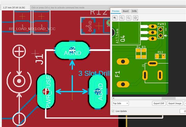
Most the shortcomings of this project are in the PCB design, these have been corrected for in the two PCB schematics using notes please. However, This project can be done in various ways many of which are better and more efficient, I chose to do it this way to maximise the space being used.
Media
ISLA Autonomous Robot
*PCBWay community is a sharing platform. We are not responsible for any design issues and parameter issues (board thickness, surface finish, etc.) you choose.
- Comments(2)
- Likes(8)
- 2 USER VOTES
- YOUR VOTE 0.00 0.00
- 1
- 2
- 3
- 4
- 5
- 6
- 7
- 8
- 9
- 10
- 1
- 2
- 3
- 4
- 5
- 6
- 7
- 8
- 9
- 10
- 1
- 2
- 3
- 4
- 5
- 6
- 7
- 8
- 9
- 10
- 1
- 2
- 3
- 4
- 5
- 6
- 7
- 8
- 9
- 10
-
9design
-
9usability
-
9creativity
-
9content

-
9design
-
9usability
-
8creativity
-
8content
 More by K Mumba
-
-
Instrumentation Input, high impedance with 16 bit 1MSPS ADC for SPI
290 0 0 -
RGB LED Matrix input module for the Framework Laptop 16
481 0 2 -
-
📦 StackBox: Modular MDF Storage Solution 📦
301 0 2 -


^yes please